Lifting mechanism of a slow-drawing groove
A technology of lifting mechanism and pulling groove, which is applied in the direction of electrolysis process, electrolysis components, etc., to achieve the effect of improving production efficiency and load-bearing capacity
- Summary
- Abstract
- Description
- Claims
- Application Information
AI Technical Summary
Problems solved by technology
Method used
Image

Examples
Embodiment 1
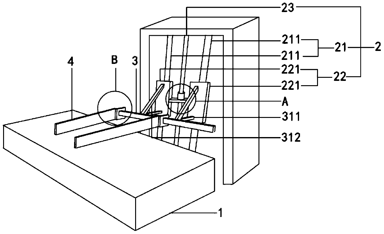
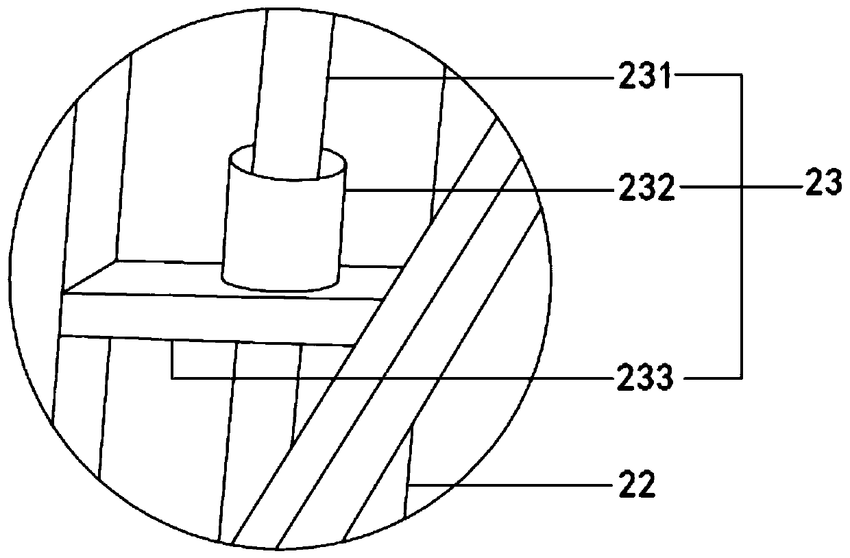
[0026] see Figure 1 to Figure 3 , the figure shows a lifting mechanism for a slow-drawing trough provided by Embodiment 1 of the present invention. Firstly, a driving mechanism 2 is provided, which is located on the side of the slow-drawing trough body 1. The driving mechanism 2 includes a guide rod assembly 21, a slide plate assembly 22 and a drive part 23, the slide assembly 22 is slidably connected to the guide rod assembly 21, the slide assembly 22 moves along the length direction of the guide rod assembly 21 under the drive of the drive part 23, and the crossbeam 3 is fixedly mounted on the slide assembly 22. The end of the frame plate 4 is detachably installed on the beam 3 , and a hanger is hoisted on the frame plate 4 .
[0027] see Figure 1 to Figure 3 , the guide rod assembly 21 includes two guide rods 211, the slide plate assembly 22 includes two slide plates 221, the guide rods 211 are fixedly installed on the ground and are perpendicular to the ground, the guide r
Embodiment 2
[0036] see Figure 1 to Figure 3 , the figure shows a lifting mechanism for a slow-drawing trough provided by Embodiment 2 of the present invention. On the basis of the above-mentioned embodiments, this embodiment further makes the following technical solutions as improvements: the driving mechanism 2 includes Guide rod assembly 21, slide plate assembly 22 and driving part 23, slide plate assembly 22 is slidably connected with guide rod assembly 21, guide rod assembly 21 comprises two guide rods 211, slide plate assembly 22 comprises two slide plates 221, is provided with guide on slide plate 221. Slot, the slide plate 221 is positioned on the guide rod 211 through the guide groove, and the inner wall of the guide groove is attached with a smooth patch, thereby reducing the friction between the guide rail and prolonging the service life of the slide plate and the guide rail. At the same time, the smooth patch is easy to replace and maintain low cost.
Embodiment 3
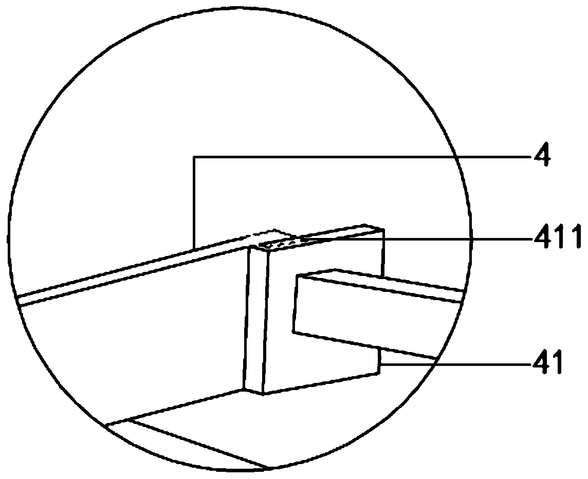
[0038] see Figure 1 to Figure 3 , the figure shows a lifting mechanism for a slow-drawing trough provided by Embodiment 3 of the present invention. On the basis of the above-mentioned embodiments, this embodiment further makes the following technical solutions as improvements: multiple shelf plates The end of 4 is detachably installed on the crossbeam 3, hanger is installed on the shelf plate 4, offers a plurality of positioning holes on the crossbeam 3, and the shelf plate 4 moves to the positioning hole place and is positioned by the latch. This positioning structure can improve the stability of the shelf during the lifting process.
PUM
 Abstract
Description
Claims
Application Information
 - R&D Engineer
- R&D Manager
- IP Professional
- Industry Leading Data Capabilities
- Powerful AI technology
- Patent DNA Extraction
Browse by: Latest US Patents, China's latest patents, Technical Efficacy Thesaurus, Application Domain, Technology Topic.
© 2024 PatSnap. All rights reserved.Legal|Privacy policy|Modern Slavery Act Transparency Statement|Sitemap