Airport pavement friction testing apparatus
An airport runway and test device technology, applied in the direction of using mechanical devices, measuring devices, instruments, etc., to avoid frictional force changes, simple operation, and accurate test results.
- Summary
- Abstract
- Description
- Claims
- Application Information
AI Technical Summary
Benefits of technology
Problems solved by technology
Method used
Image

Examples
Embodiment 1
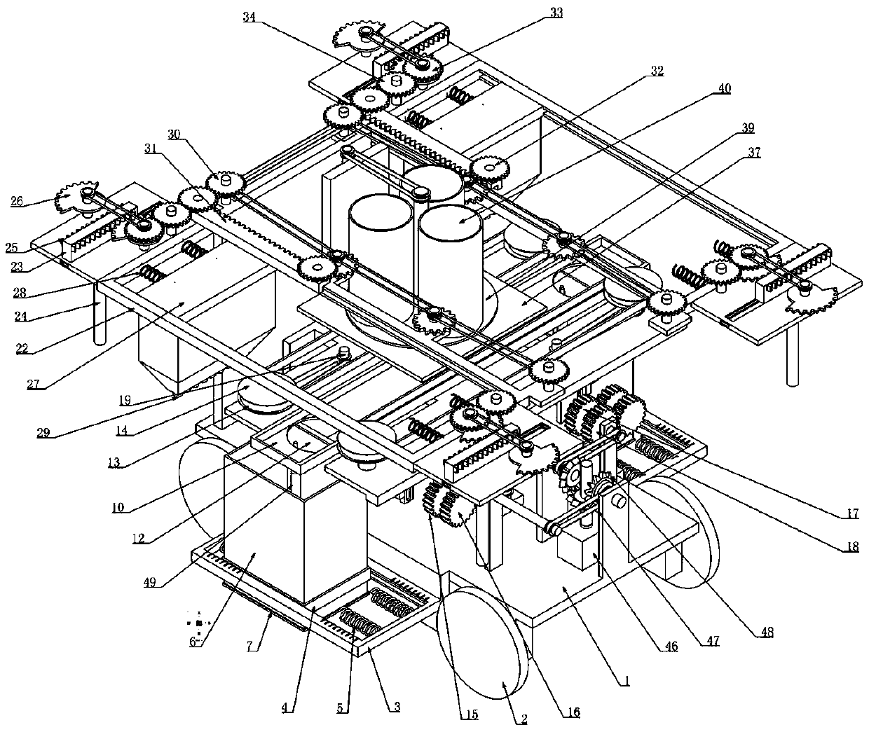
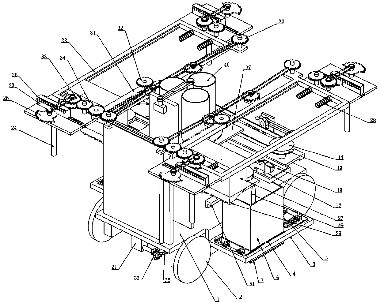
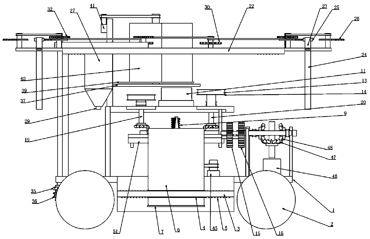
[0035] Embodiment one, combined with the attached Figure 1-14 , airport runway pavement friction test device, including car body 1 and wheel 2, wheel 2 is divided into front and back two groups, one group includes wheel 2 and wheel hub, load-bearing shaft, etc., is the prior art, will not go into details here, its It is characterized in that the front and rear ends of the vehicle body 1 are respectively connected with rectangular frames 3, the rectangular frames 3 are installed on the front and rear sides of the vehicle body 1, extend out of the vehicle body 1, and are respectively arranged on the outer sides of the front and rear wheels 2. A moving frame 4 is connected horizontally in the rectangular frame 3, and sliding grooves are provided on the lateral side walls of the rectangular frame 3, and sliding tracks cooperating with the sliding grooves are connected on the lateral lateral sides of the moving frame 4, so that the moving frame 4 can only move along the transverse di
Embodiment 2
[0039] Embodiment two, on the basis of embodiment one, in conjunction with the attached Figure 1-14The cleaning and showering device includes a bracket 22 installed horizontally on the upper end of the vehicle body 1 and placed directly above the storage box 6, the bracket 22 is connected to the upper end of the vehicle body 1, and the left and right ends of the bracket 22 slide longitudinally respectively Connect a mobile plate 23, the sliding connection mode of the mobile plate 23 and the support 22 adopts a cross-shaped connection mode, so that the mobile plate 23 can only move along the longitudinal direction of the support 22, and the lower end of the mobile plate 23 is connected to a The sleeve 24 of cleaning device is installed, and cleaning equipment is installed in the sleeve 24, and the ground is cleaned, and it should be noted here that the cleaning device must be arranged on the far-end direction on both sides of the rectangular frame 3, so that it can The measuring
Embodiment 3
[0041] Embodiment three, on the basis of embodiment one, in conjunction with the attached Figure 1-14 The storage device includes a partition 37 installed on the vehicle body 1 and placed above the chute 10, the partition 37 is provided with a circular channel 38 matching the counterweight 11, the described A circular plate 39 is rotatably connected to the partition 37, and three sets of storage cylinders 40 are evenly distributed along the circumferential direction on the circular plate 39. The lower ends of the storage cylinders 40 and the circular plate 39 form a transparent hole-like structure, which meets the requirements of the counterweight. 11 can be dropped into the chute 10 from the storage cylinder 40 through the circular through groove 38, and the rotating shaft of the circular plate 39 is connected to the drive motor 41 installed on the vehicle body 1 through a belt, and the corresponding storage cylinder 40 After the counterweight 11 is used up, the drive motor 41
PUM
 Abstract
Description
Claims
Application Information
 - R&D Engineer
- R&D Manager
- IP Professional
- Industry Leading Data Capabilities
- Powerful AI technology
- Patent DNA Extraction
Browse by: Latest US Patents, China's latest patents, Technical Efficacy Thesaurus, Application Domain, Technology Topic.
© 2024 PatSnap. All rights reserved.Legal|Privacy policy|Modern Slavery Act Transparency Statement|Sitemap