Heliostat calibration system and method
A heliostat and a technology to be calibrated, which is applied in the field of solar power generation, and can solve the problems of complex processing methods, affecting the calibration efficiency of heliostats, and long consumption time.
- Summary
- Abstract
- Description
- Claims
- Application Information
AI Technical Summary
Problems solved by technology
Method used
Image

Examples
Embodiment 1
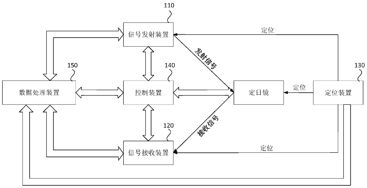
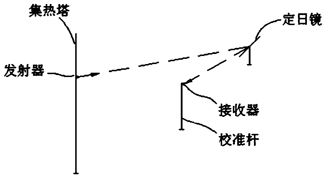
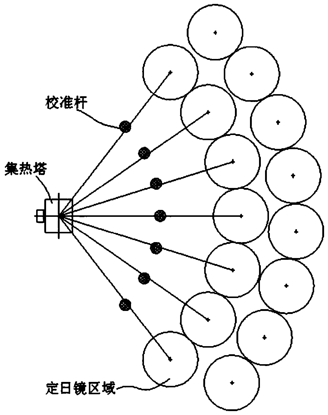
[0048] figure 1 It is a structural block diagram of the heliostat calibration system provided in Embodiment 1 of the present application. This embodiment can be adapted to the situation of calibrating each heliostat in the heliostat field. The system can be composed of software and / or hardware It can be realized in a manner, and the method for calibrating the heliostat provided in this application can be executed.
[0049] like figure 1 As shown, the calibration system of the heliostat includes: at least one signal transmitting device 110, at least one signal receiving device 120, a positioning device 130, a control device 140 and a data processing device 150; wherein:
[0050] The positioning device 130 is configured to determine the spatial positions of the at least one signal transmitting device 110, the at least one signal receiving device 120, and the heliostat to be calibrated, and the at least one signal transmitting device 110, the at least one signal receiving device
Embodiment 2
[0084] Figure 9 It is a flow chart of the calibration method of the heliostat provided in Embodiment 2 of the present application. The method provided in this embodiment may be implemented by the calibration system of the heliostat described above.
[0085] like Figure 9 As shown, the calibration system and method of the heliostat include:
[0086] S910. Determine the spatial positions of the at least one signal transmitting device, at least one signal receiving device, and the heliostat to be calibrated by the positioning device, and set the at least one signal transmitting device, at least one signal receiving device, and the positioning device to be calibrated The spatial position of the heliostat is uploaded to the data processing device.
[0087] S920. Send a control signal to the at least one signal transmitting device and at least one signal receiving device by the control device, so as to control the signal transmitting device and the signal receiving device to trans
PUM
 Abstract
Description
Claims
Application Information
 - R&D Engineer
- R&D Manager
- IP Professional
- Industry Leading Data Capabilities
- Powerful AI technology
- Patent DNA Extraction
Browse by: Latest US Patents, China's latest patents, Technical Efficacy Thesaurus, Application Domain, Technology Topic.
© 2024 PatSnap. All rights reserved.Legal|Privacy policy|Modern Slavery Act Transparency Statement|Sitemap