Practical solar pest killing lamp

A solar-powered insecticidal lamp, a practical technology, is applied in the device, application, animal husbandry and other directions of catching or killing insects, and can solve the problems of easy destruction of solar panels, frequent dismantling of insect storage devices, and unstable installation of lamps, etc. Avoid frequent disassembly, improve work efficiency and prolong service life

Inactive Publication Date: 2019-10-29
临泽县众志科技开发有限公司
View PDF0 Cites 0 Cited by
  • Summary
  • Abstract
  • Description
  • Claims
  • Application Information

AI Technical Summary

Benefits of technology

This patented technology provides an improved way for storing pests during inclement weather or when they may damage their equipment due to high levels of sunlight exposure. It includes flip-flop lamps that use magnetic force between two parts instead of just holding them together. These devices have a special design where there're no easy accessory like cords attached at any points on its structure. Additionally, these lights provide better stability over longer periods than traditional methods without adding extra components such as brackets or other fasteners. Overall, this innovation enhances safety measures while maintaining efficient operation time and extending lifespan of the LED (Light Emitting Diode) type bug trap.

Problems solved by technology

This patented technical solution describes an improved type of electricity for killing harmful organisms called mothers during farming operations. These lights are designed specifically targeted towards certain types of insectes like spiders (tiny rodents) which attract these nymphocytes). By controlling their behavior through photosensitizing agents, they cannot escape from crops due to lack of nutrients needed for growth. They work well even when there aren’t any other things around us such as plants themselves.

Method used


Image

  • Practical solar pest killing lamp
  • Practical solar pest killing lamp
  • Practical solar pest killing lamp

Examples


Embodiment Construction

[0014] The following will clearly and completely describe the technical solutions in the embodiments of the present invention with reference to the accompanying drawings in the embodiments of the present invention. Obviously, the described embodiments are only some, not all, embodiments of the present invention. Based on the embodiments of the present invention, all other embodiments obtained by persons of ordinary skill in the art without making creative efforts belong to the protection scope of the present invention.

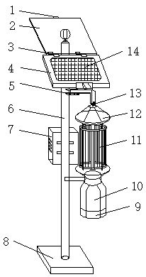
[0015] see figure 1 and figure 2 , the present invention provides a practical solar insecticidal lamp technical solution: a practical solar insecticidal lamp, including a support frame 6, one end of the support frame 6 is provided with a chassis 8 and the other end is provided with a battery board bottom plate 4, the battery board bottom plate The front surface of 4 is provided with a light-receiving plate 14, one side of the battery board bottom plate 4 is pro


PUM


Abstract

The invention discloses a practical solar pest killing lamp. The lamp comprises a support frame, wherein a base plate is arranged at one end of the support frame, and a cell panel base plate is arranged at the other end; a light accepting plate is arranged on the front surface of the cell panel base plate; hinges are arranged at the joint of a protection plate and the cell panel base plate; a pullring is arranged on one side of the protection plate; a bolt hole is formed in a fixing plate; the hinges are arranged at the upper end of the cell panel base plate; magnets are arranged on the backsurface of the protection plate and the upper end of the support frame respectively; the pull ring is arranged at the upper end of the protection plate, and can be connected with a rope end and matched with the magnets to control opening and closing of the protection plate; a pest storage base is arranged at the lower end of a pest storage; a fixing slot is formed in one end of the fixing plate. Therefore, the solar light accepting plate can be effectively prevented from being damaged by heavy substances, the lamp can also be fixed and prevented from being destroyed by heavy wind and the like,and the pest storage can also be prevented from being frequently dismounted, so that work efficiency is improved, and the service life of the pest killing lamp is prolonged.

Description


Claims


Application Information

Patent Timeline
Owner 临泽县众志科技开发有限公司
Why Eureka
Try Eureka