Garbage decomposing treatment system
A technology for decomposition treatment and garbage, applied in special forms of dry distillation, gasification process, petroleum industry, etc., can solve the problems of flue gas purification treatment and emission burden, land occupation, groundwater resource threat, etc., and achieve the effect of optimizing heating effect.
- Summary
- Abstract
- Description
- Claims
- Application Information
AI Technical Summary
Problems solved by technology
Method used
Image

Examples
Example Embodiment
[0036] Example 1:
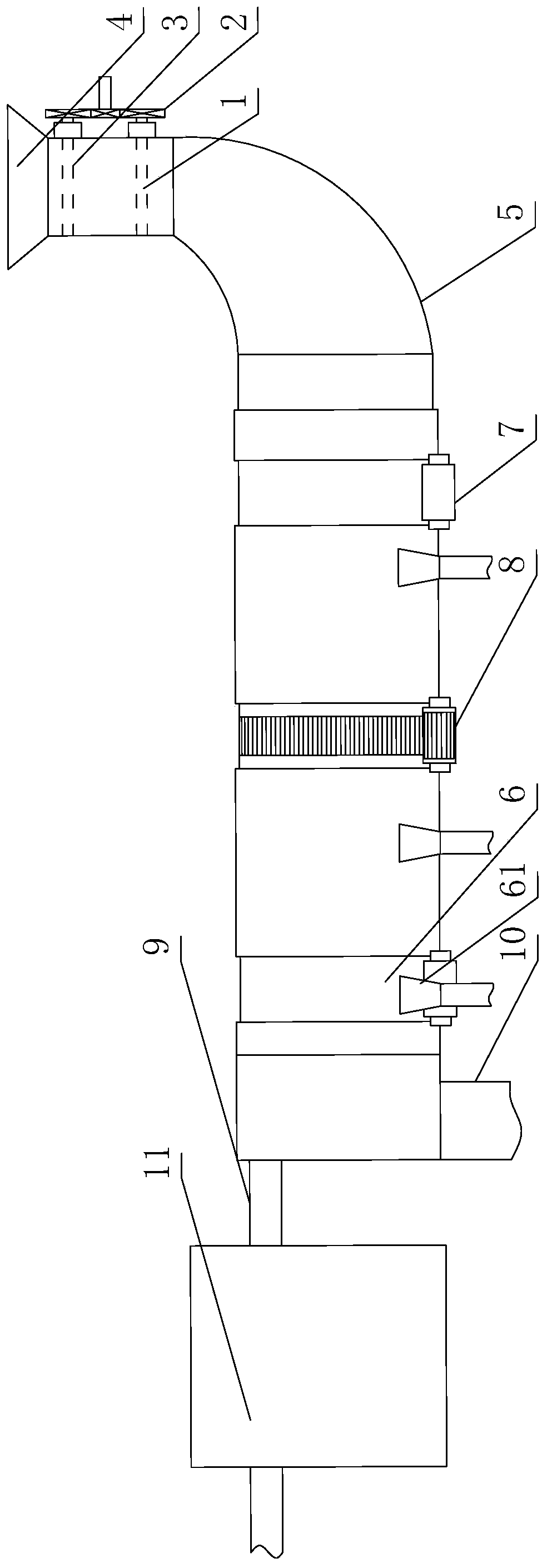
[0037] Such as figure 1 As shown, the garbage decomposition treatment system includes a treatment furnace, the treatment furnace is a pyrolysis furnace or a gasification furnace, the treatment furnace includes a furnace body 6, and the waste inlet end of the furnace body 6 is connected with a feeding device, The material output end of the furnace body 6 is connected with a discharging device, and the furnace body 6 is in the shape of a tube with openings at both ends, wherein the opening at one end is used as the material feeding end, and the opening at the other end is used as the material discharging end ;
[0038] The outlet end of the feeding device is docked with the material feeding end, the inlet end of the discharging device is docked with the material discharging end, and the above docking is all rotatable docking: in the feeding device, the discharging device The device is fixed in space, and when the furnace body 6 rotates around its own axis, the feed
Example Embodiment
[0042] Example 2:
[0043] This embodiment is further defined on the basis of embodiment 1. The feeding device includes a feeding pipe 5 with an outlet end butting with the material feeding end, and a first valve plate 1 is installed on the feeding pipe 5 And a second valve plate 3, the first valve plate 1 and the second valve plate 3 are both used to control the conduction state of the feed pipe 5;
[0044] In the extension direction of the feed pipe 5, the first valve plate 1 and the second valve plate 3 are installed at different positions;
[0045] It also includes a linkage device 2, which is used to link the first valve plate 1 and the second valve plate 3, so that both of the first valve plate 1 and the second valve plate 3 are in the cut-off process. When the feed pipe 5 is in the state, the other is in a state of conducting the feed pipe 5. For waste treatment using pyrolysis furnaces or gasifiers, oxygen has an important effect on the generation of dioxins: for example, when
Example Embodiment
[0058] Example 3:
[0059] This embodiment is further limited on the basis of embodiment 1, such as figure 1 As shown, as a specific form of the discharging device, it is set as follows: the discharging device includes a discharging barrel with an inlet end butting with the material discharging end, and a solid discharge port 10 is provided at the bottom of the discharging barrel, A gas discharge pipe 9 is connected to the top of the discharge cylinder, and also includes a dust removal device 11 connected in series to the gas discharge pipe 9. In this solution, after the processed material enters the discharge cylinder from the material discharge end of the furnace body 6, the solid material is input from the solid discharge port 10, and the gaseous material is output from the gas discharge pipe 9, which is set to include the dust removal The device 11 can make the gas output by the system cleaner, so as to facilitate subsequent pressurized transportation for use as a combustible g
PUM
 Abstract
Description
Claims
Application Information
 - R&D Engineer
- R&D Manager
- IP Professional
- Industry Leading Data Capabilities
- Powerful AI technology
- Patent DNA Extraction
Browse by: Latest US Patents, China's latest patents, Technical Efficacy Thesaurus, Application Domain, Technology Topic.
© 2024 PatSnap. All rights reserved.Legal|Privacy policy|Modern Slavery Act Transparency Statement|Sitemap