Double-charger charging circuit

A charging circuit and double charger technology, applied in battery circuit devices, current collectors, circuit devices, etc., can solve the problems of high cost, increased cost, and large power consumption of the charging circuit, and achieve low cost, increased power, and improved charging efficiency effect

Pending Publication Date: 2019-12-10
闻泰科技(无锡)有限公司
View PDF0 Cites 1 Cited by
  • Summary
  • Abstract
  • Description
  • Claims
  • Application Information

AI Technical Summary

Problems solved by technology

[0002] At present, electronic devices such as laptops usually have only one charging port. If fast charging is to be achieved, it can only be achieved by increasing the

Method used


Image

  • Double-charger charging circuit
  • Double-charger charging circuit

Examples


Example Embodiment

[0020] The technical solutions in the embodiments of the present invention will be clearly and completely described below in conjunction with the accompanying drawings in the embodiments of the present invention. Obviously, the described embodiments are only a part of the embodiments of the present invention, rather than all the embodiments. The components of the embodiments of the present invention generally described and illustrated in the drawings herein may be arranged and designed in various different configurations. Therefore, the following detailed description of the embodiments of the present invention provided in the accompanying drawings is not intended to limit the scope of the claimed invention, but merely represents selected embodiments of the present invention. Based on the embodiments of the present invention, all other embodiments obtained by those skilled in the art without creative work shall fall within the protection scope of the present invention.

[0021] Pleas


PUM


Abstract

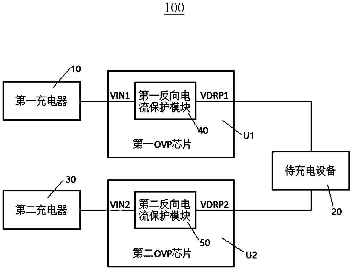
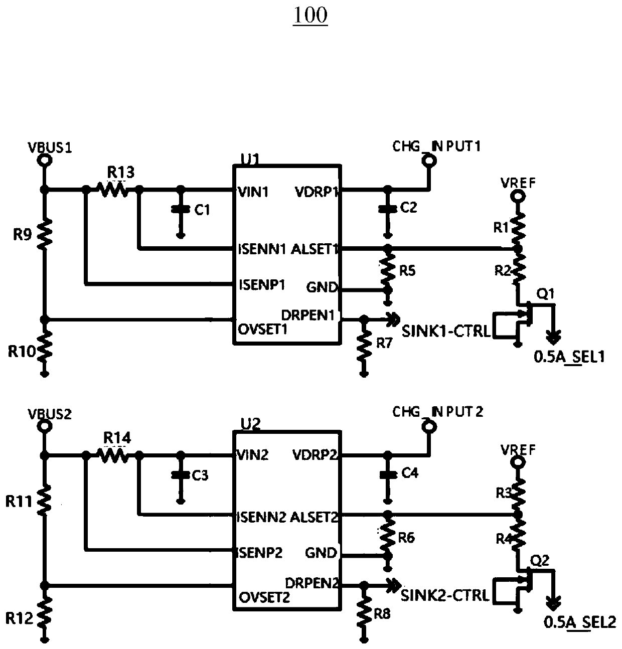
The invention provides a double-charger charging circuit. The charging circuit comprises a first OVP chip and a second OVP chip. The first OVP chip comprises a first voltage input pin and a first voltage output pin. The second OVP chip comprises a second voltage input pin and a second voltage output pin. The first voltage input pin is used for being connected with a first charger, and the first voltage output pin is used for being connected with to-be-charged equipment. The second voltage input pin is used for being connected with a second charger, and the second voltage output pin is used forbeing connected with the to-be-charged equipment. According to the double-charger charging circuit provided by the invention, when the two chargers charge the to-be-charged equipment at the same time, the charger with relatively high power is preferentially used to charge the to-be-charged equipment, so that the charging efficiency is improved. If the voltages of the two chargers are equal, the to-be-charged equipment is charged by the two chargers at the same time, so that the power of an input power supply is further improved. A quick charging function can be realized, and the cost of the charging circuit is relatively low.

Description


Claims


Application Information

Patent Timeline
Owner 闻泰科技(无锡)有限公司
Why Eureka
Try Eureka