Hazardous gas leakage detection alarm device

A technology for leak detection and dangerous gas, which is used in measuring devices, liquid/vacuum measurement for liquid tightness, instruments, etc. The effect of large detection range and simple operation

Inactive Publication Date: 2020-03-06
XUZHOU NORMAL UNIVERSITY
View PDF8 Cites 0 Cited by
  • Summary
  • Abstract
  • Description
  • Claims
  • Application Information

AI Technical Summary

Problems solved by technology

At present, the hazardous gas detection equipment has its own buzzer, but the buzzer is small and the sound is very small. When it is use

Method used


Image

  • Hazardous gas leakage detection alarm device
  • Hazardous gas leakage detection alarm device
  • Hazardous gas leakage detection alarm device

Examples


Embodiment Construction

[0017] The following will clearly and completely describe the technical solutions in the embodiments of the present invention with reference to the accompanying drawings in the embodiments of the present invention. Obviously, the described embodiments are only some, not all, embodiments of the present invention. Based on the embodiments of the present invention, all other embodiments obtained by persons of ordinary skill in the art without making creative efforts belong to the protection scope of the present invention.

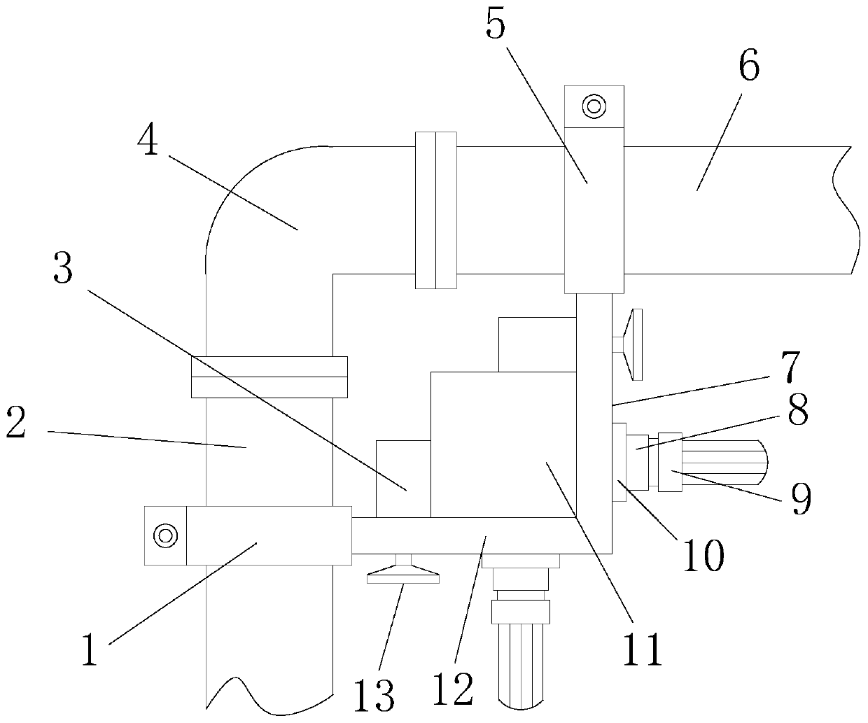
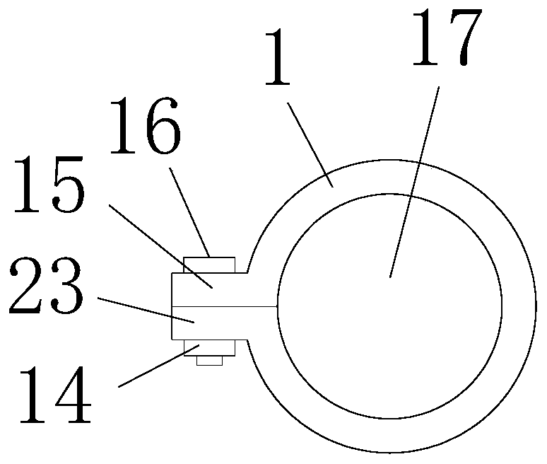
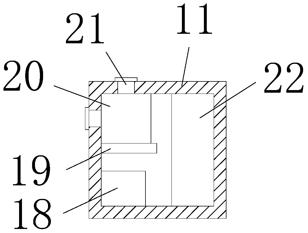
[0018] see Figure 1~3 , the present invention provides a technical solution:

[0019] The dangerous gas leakage detection and alarm device includes a horizontal pipe 6 and a vertical pipe 2. An elbow 4 is connected between the left end of the horizontal pipe 6 and the upper end of the vertical pipe 2. The horizontal pipe 6 and the vertical pipe 2 are arranged vertically. The horizontal tube 6 is covered with an upper collar 5, the vertical tube 2 is covered wit


PUM


Abstract

The invention provides a hazardous gas leakage detection alarm device. The device comprises a transverse pipe and a vertical pipe. A bent pipe is connected between the left end of the transverse pipeand the upper end of the vertical pipe. The transverse pipe and the vertical pipe are vertically arranged. The transverse pipe is sleeved by an upper lantern ring. The vertical pipe is sleeved by a left lantern ring. The lower end of the upper lantern ring is fixedly connected with a vertical plate. The right end of the left lantern ring is connected with a transverse plate. The lower end of the vertical plate is fixedly connected with the right end of the transverse plate. Detection boxes are installed on the upper side of the transverse plate and the left side of the vertical plate. The structure is simple and clear and easy to understand. Suction fans are installed above and on the left side of the detection boxes to suck gas near the transverse pipe and the vertical pipe, so that the detection range is enlarged. A pollutant detector in each detection box sucks in surrounding gas through a gas inlet pipe. If each detector detects that hazardous gas exceeds the standard, a signal istransmitted to a controller through a sensor, and the controller controls an alarm lamp to be turned on. Leakage troubleshooting is carried out. Troubleshooting is carried out within the range of eachdetection box. The operation is easy.

Description


Claims


Application Information

Patent Timeline
Owner XUZHOU NORMAL UNIVERSITY
Why Eureka
Try Eureka