Motor overheating protection method

An overheat protection and current technology, applied in emergency protection circuit devices, automatic disconnection emergency protection devices, electrical components, etc., can solve problems such as incomplete detection of current and voltage, and achieve the effect of reducing damage

Pending Publication Date: 2020-03-27
龙胜和
View PDF0 Cites 0 Cited by
  • Summary
  • Abstract
  • Description
  • Claims
  • Application Information

AI Technical Summary

Problems solved by technology

[0004] The purpose of the present invention is to provide a method for motor overheat protection, thereby overcoming the existing shortcomings of only detecting current and voltage for motor overheat protection

Method used


Image

  • Motor overheating protection method
  • Motor overheating protection method

Examples


Example Embodiment

[0037] The following describes the technical solutions of the present invention clearly and completely with reference to the drawings in the embodiments of the present invention. Obviously, the described embodiments are only a part of the embodiments of the present invention, rather than all the embodiments. Based on the embodiments of the present invention, all other embodiments obtained by those of ordinary skill in the art without creative work shall fall within the protection scope of the present invention.

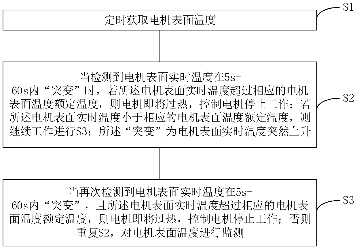
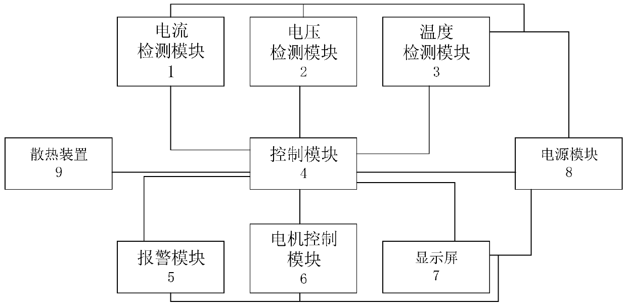
[0038] Such as figure 1 with figure 2 As shown, a motor overheating protection method provided by the present invention includes the following steps:

[0039] S1. Obtain the motor surface temperature regularly through infrared temperature measurement equipment, temperature detection module or motor overheating protection device, and determine the motor surface that is most likely to detect temperature changes when the motor is overheated according to the motor temperature wh


PUM


Abstract

The invention discloses a motor overheating protection method, and relates to the field of motor protection equipment. The method comprises the steps of obtaining the surface temperature of a motor regularly, when the situation that the real-time temperature of the surface of the motor suddenly changes within 5s-60s is detected, and if the real-time temperature of the surface of the motor exceedsa corresponding rated temperature of the surface temperature of the motor, judging that the motor is about to be overheated, and controlling the motor to stop working; if the real-time temperature ofthe surface of the motor is lower than the corresponding rated temperature of the surface temperature of the motor, continuing to work, wherein the abrupt change means that the real-time temperature of the surface of the motor suddenly rises; then, when it is detected that the real-time temperature of the surface of the motor suddenly changes within 5-60 s again, and the real-time temperature of the surface of the motor exceeds the corresponding rated temperature of the surface temperature of the motor, judging that the motor is about to be overheated, and controlling the motor to stop working; otherwise, judging repeatedly, so that the overheating of the motor is prevented in advance by monitoring the surface temperature of the motor, instead of processing until the motor is burnt out, and at the same time, the greater damage to the motor due to the overheating of the motor is also reduced.

Description


Claims


Application Information

Patent Timeline
Owner 龙胜和
Why Eureka
Try Eureka