Power control method for standby power supply mode of electric equipment and electric equipment
A technology for electrical equipment and backup power, which is applied in emergency power arrangements, battery circuit devices, collectors, etc., can solve problems such as reducing user experience, generator or inverter overload shutdown, etc., to achieve the effect of guaranteeing user experience
- Summary
- Abstract
- Description
- Claims
- Application Information
AI Technical Summary
Benefits of technology
Problems solved by technology
Method used
Image

Examples
Embodiment 1
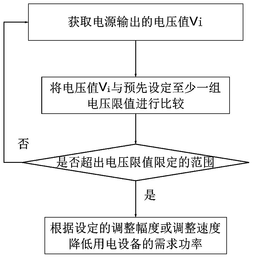
[0054] refer to figure 1 , a power control method for standby power supply mode of electric equipment, comprising the following steps:
[0055] Step 1, obtain the voltage value V of the power output at any time i ; In this embodiment, the electrical equipment can obtain the voltage value V of the power output once every T time interval i; The power supply is commercial power, or generator, or UPS and inverter;
[0056] Step 2, the voltage value V at this moment i Compared with at least one set of preset voltage limits; wherein, each set of voltage limits includes a high voltage limit higher than normal voltage and a low voltage limit lower than normal voltage; judging the voltage value V i Whether it exceeds the range defined by the voltage limit, if not, return to step 1, if exceeded, enter step 3;
[0057] Step 3, reducing the required power of the electrical equipment according to the set adjustment range or adjustment speed.
[0058] After the required power of the elect
Embodiment 2
[0065] On the basis of Embodiment 1, set according to the expected configuration of the electrical equipment and the expected use environment; set the number of groups of required voltage limit values, and this embodiment includes at least 2 groups of voltage limit values;
[0066] There is an adjustment range or adjustment speed corresponding to each group of voltage limit values;
[0067] In step 2, judge the voltage value V i Whether it is beyond the range defined by the voltage limit is to judge the voltage value V i Is it satisfied:
[0068] exceeds any one or more of the high voltage limits in absolute value, or
[0069] Absolute value below any one or more of the low voltage limits;
[0070] If not satisfied, the voltage value V i Does not exceed the limit range; if satisfied, the voltage value V i beyond the limits;
[0071] In step 2, the voltage value V i Multiple voltage limits may be exceeded at the same time. Therefore, in step 3, reduce the power demand of th
Embodiment 3
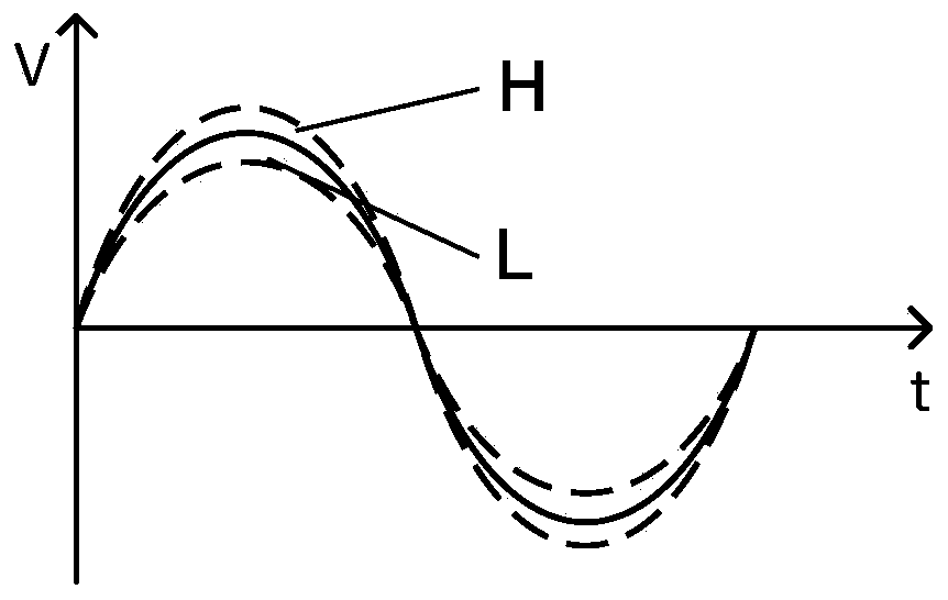
[0081] In this embodiment, on the basis of the second embodiment, setting two sets of voltage limit values is taken as an example for illustration.
[0082] refer to Figure 4 , in this embodiment, the high voltage limit of the first high limit curve H1 is V 1_H , the high voltage limit of the second high limit curve H2 is V 2_H ;The low voltage limit of the first low limit curve L1 is V 1_L , the low voltage limit of the second low limit curve L2 is V 2_L ;
[0083] In step 2, judge the voltage value V at any time i Whether it exceeds the range defined by the voltage limit includes:
[0084] If the moment V 1_L ≤V i ≤V 1_H , then the required power of the electrical equipment will not be adjusted;
[0085] If the moment V 2_L ≤V i 1_L or V 1_H i ≤V 2_H , then control the electrical equipment to reduce the required power of the electrical equipment at the set first adjustment speed or first adjustment range;
[0086] If the moment V i 2_L or V i >V 2_H , the el
PUM
 Abstract
Description
Claims
Application Information
 - R&D Engineer
- R&D Manager
- IP Professional
- Industry Leading Data Capabilities
- Powerful AI technology
- Patent DNA Extraction
Browse by: Latest US Patents, China's latest patents, Technical Efficacy Thesaurus, Application Domain, Technology Topic.
© 2024 PatSnap. All rights reserved.Legal|Privacy policy|Modern Slavery Act Transparency Statement|Sitemap