Device and method for measuring diffraction efficiency of a diffraction element

A diffraction element and diffraction efficiency technology, which is applied in the field of optical measurement, can solve the problems of increasing the number of points taken, increasing the measurement time, reducing work efficiency, etc., and achieves the effect of accurate test results

Active Publication Date: 2020-04-24
CHANGCHUN INST OF OPTICS FINE MECHANICS & PHYSICS CHINESE ACAD OF SCI
View PDF10 Cites 0 Cited by
  • Summary
  • Abstract
  • Description
  • Claims
  • Application Information

AI Technical Summary

Benefits of technology

This patented technology includes two different devices - an Interference Meter (I) which measures how well it collects reflected sunlight from various surfaces while also analyzing its properties like brightness or color temperature. An Optic Powermeter(II), located on top of this I'm used to measure the amount of transmitting solar rays through specific materials such as glass windows. By combining these measurements together they provide better accuracy than just looking into each other individually.

Problems solved by technology

This patented technical problem addressed in the patents relates to improving the accuracy or speed when determining how well a specific type of light beam interacted with certain types of materials like gratings during their formation into desired patterns.

Method used


Image

  • Device and method for measuring diffraction efficiency of a diffraction element
  • Device and method for measuring diffraction efficiency of a diffraction element
  • Device and method for measuring diffraction efficiency of a diffraction element

Examples


Embodiment 1

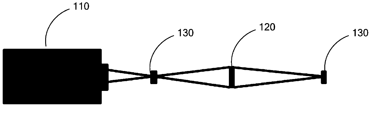
[0026] see figure 1 , is a structural schematic diagram of a measuring device for the diffraction efficiency of a diffraction element provided by the present invention, including: an interferometer 110, a diffraction element 120 and an optical power meter 130, the interferometer 110 selects a spherical standard mirror, and the interferometer 110 to The spherical wave focus position is R, and the distance between the interferometer 110 and the diffraction element 120 is S. in:

[0027] The laser beam emitted by the interferometer 110 enters the diffraction element 120 and is focused by the diffraction element 120 .

[0028] Further, the light in the test environment is turned off to minimize the interference of background light, and the background stray light energy is recorded by the optical power meter 130, and the count is E 0 .

[0029] When the laser beam emitted by the interferometer 110 enters the diffraction element 120, the optical power meter detects the total inciden

Embodiment 2

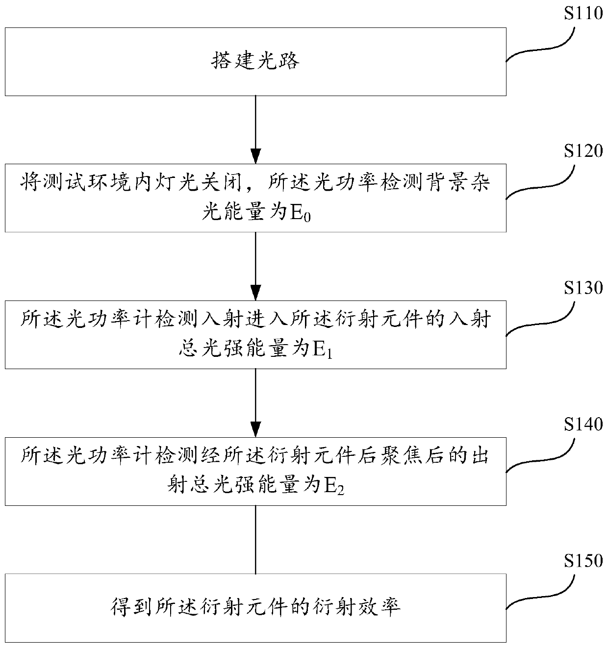
[0037] see figure 2 , a structural schematic diagram of a measuring method of a measuring device for the diffraction efficiency of a diffraction element provided by the present invention, comprising the following steps:

[0038] Step S110: Build an optical path, the optical path includes an interferometer, a diffraction element, and an optical power meter, the position of the interferometer to the spherical wave focus is R, the distance between the interferometer and the diffraction element is S, and the interferometer The outgoing laser beam enters the diffraction element and is focused after passing through the diffraction element.

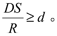
[0039] Further, in order to ensure that the spherical wave emitted by the interferometer can cover the diffraction element 120, it is assumed that the distance from the focal point of the spherical wave emitted by the standard mirror of the interferometer is R, and the distance from the focal point to the diffraction element is S, which needs to s


PUM


Abstract

The invention provides a device and a method for measuring diffraction efficiency of a diffraction element. The device comprises an interferometer, a diffraction element and an optical power meter. The optical power meter is used for detecting that the background stray light energy is E0; the optical power meter detects that the total incident light intensity energy entering the diffraction element is E1; the optical power meter detects that the total emergent light intensity energy after being focused by the diffraction element is E2; the diffraction efficiency of the diffraction element is shown as follows. According to the device and the method for measuring the diffraction efficiency of the diffraction element, the characteristic that the diffraction element can converge light is applied, the interferometer equipment is combined, the diffraction efficiency of the whole diffraction element can be obtained through one-time measurement and the test result is more accurate.

Description


Claims


Application Information

Patent Timeline
Owner CHANGCHUN INST OF OPTICS FINE MECHANICS & PHYSICS CHINESE ACAD OF SCI
Why Eureka
Try Eureka