Suction cleaning device with chamber cover closing filter chamber

A technology for cleaning equipment and filter chambers, applied in cleaning equipment, suction filters, vacuum cleaners, etc., and can solve problems such as user discomfort and discomfort

Active Publication Date: 2020-04-28
VORWERK & CO INTERHOLDING GMBH
View PDF7 Cites 0 Cited by
  • Summary
  • Abstract
  • Description
  • Claims
  • Application Information

AI Technical Summary

Benefits of technology

This patented design allows for easy insertion and disassembly of filters while maintaining their functionality during use. It includes a flexible covering material attached to the inside surface of the cleaner's body frame, allowing users to easily replace them if needed. Additionally, the space available within the holder unit makes it easier to dispose after usage. Overall, these technical features improve efficiency and convenience compared to existing designs.

Problems solved by technology

This patented technical problem addressed in this patents relates to finding ways to easily change filters used during suckling cleanings without having to go through all over again when replacing them due to their awkwardness around being located within the space covered by the cleaner's body.

Method used


Image

  • Suction cleaning device with chamber cover closing filter chamber
  • Suction cleaning device with chamber cover closing filter chamber
  • Suction cleaning device with chamber cover closing filter chamber

Examples


Embodiment Construction

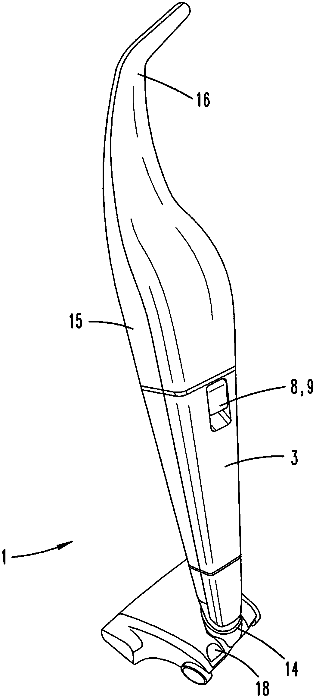
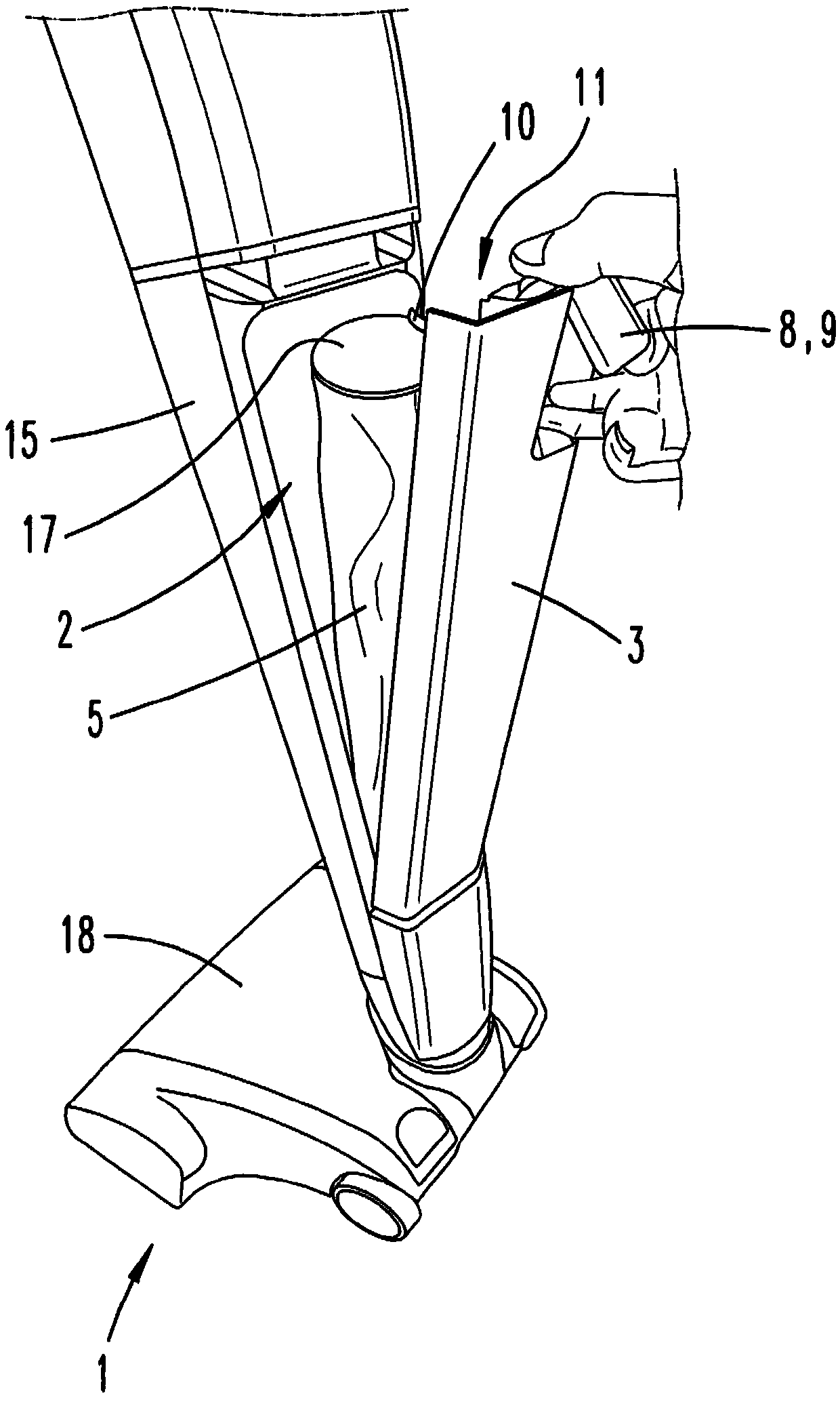
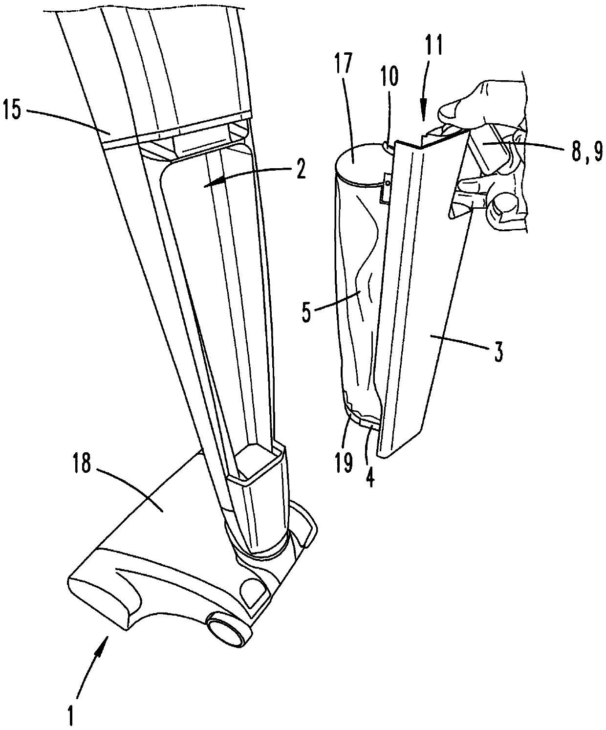
[0022] figure 1 An extraction cleaning device 1 according to the invention is shown, which is designed here, for example, as a battery-operated vacuum cleaner. The suction cleaning device 1 has a housing 15 with a shaped handle 16 (see figure 2 ) for guiding the suction cleaning device 1 by the user. On the side of the suction cleaning device 1 facing away from the handle 16 , the housing 15 has a suction connection 14 to which an accessory, here for example a bottom suction nozzle 18 , is connected.

[0023] The suction cleaning device 1 has a motor-fan unit, not shown in detail, which is used to suck suction material into the suction cleaning device 1 . For example, a switch (not shown) for activating and deactivating the motor-fan unit and a selector switch (not shown) are located on the handle 16 by means of which different power levels of the motor-fan unit can be selected.

[0024] Furthermore, the suction cleaning device 1 has a filter chamber 2 which can be closed wit


PUM


Abstract

The invention relates to a suction cleaning device (1) having a filter chamber (2) and a chamber cover (3) which closes the filter chamber (2). The chamber cover (3) has a filter bag storage part (4)for fastening a filter bag (5). The aim of the invention is to allow the filter bag (5) to be replaced comfortably. Proposed herein is a suggestion, the chamber cover (3) is provided with a cover edgearea (6), the chamber cover (3) is detachably supported on an adapted chamber edge region (7) of the filter chamber (2) by means of the cover edge region (6) in the absence of auxiliary means, and atleast one partial region of the cover edge region (6) is engaged with the chamber edge region (7) of the filter chamber (2) in such a way so that the chamber cover (3) can be rotated relative to thefilter chamber (2).

Description


Claims


Application Information

Patent Timeline
Owner VORWERK & CO INTERHOLDING GMBH
Why Eureka
Try Eureka