Dehumidifying system and fresh air dehumidifying machine
A technology of dehumidification part and fresh air passage, applied in the field of air conditioning, can solve the problems of poor condensation performance and evaporation performance, and achieve the effect of improving condensation performance and evaporation performance
- Summary
- Abstract
- Description
- Claims
- Application Information
AI Technical Summary
Problems solved by technology
Method used
Image

Examples
Embodiment 2
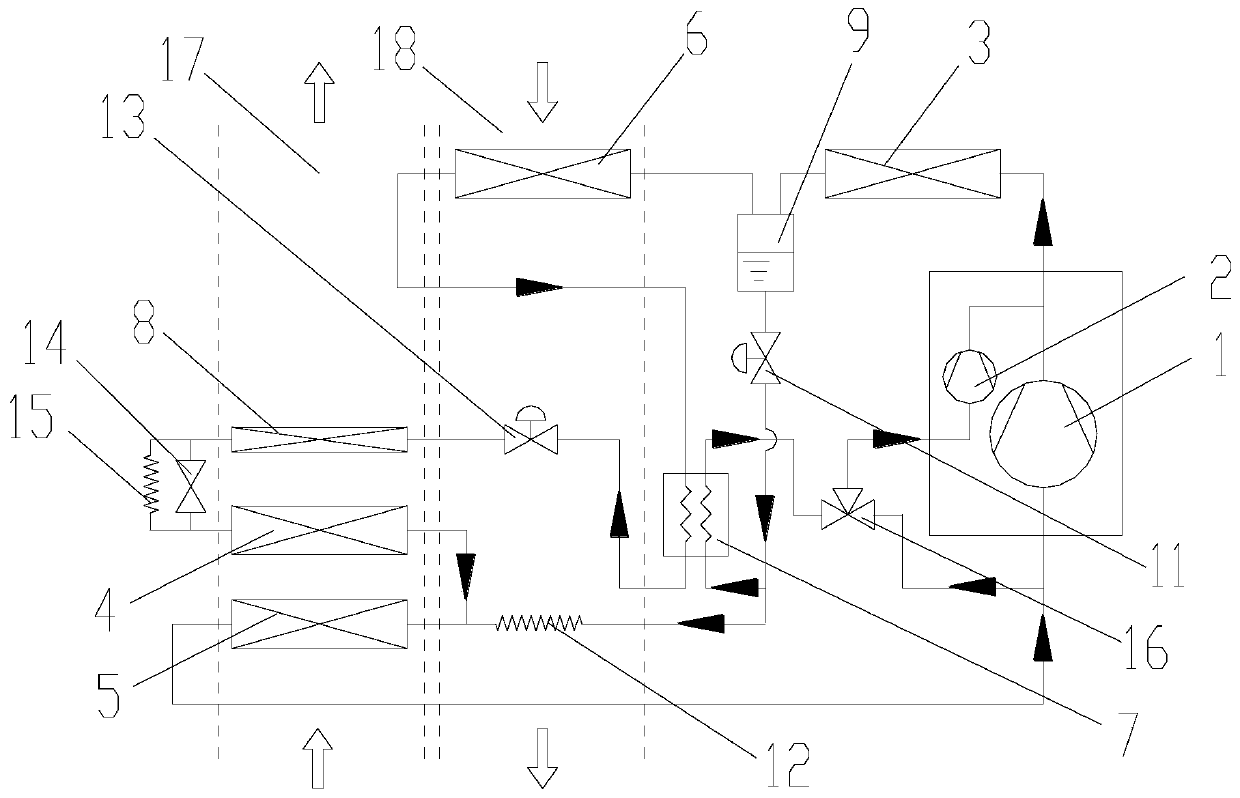
[0055] Such as figure 2 As shown, the difference from Embodiment 1 is that the return pipe is provided with a second branch structure to divide the return pipe into a third branch and a fourth branch, the third branch and the first compression chamber 1 The air inlet is connected, the fourth branch is connected with the second branch through the third branch structure 16 , and the outlet end of the third branch structure 16 is connected with the air supply port of the second compression chamber 2 . By setting the third flow distribution structure 16, the first compression chamber 1 and the second compressor can be connected in parallel, and two modes of parallel compression and parallel compression can be switched according to actual conditions.
[0056] Further, the second branch structure is a three-way pipe, and the third branch structure 16 is a three-way valve, wherein the three-way valve includes a first inlet and a second inlet, and the first inlet is connected to the sec
Embodiment 3
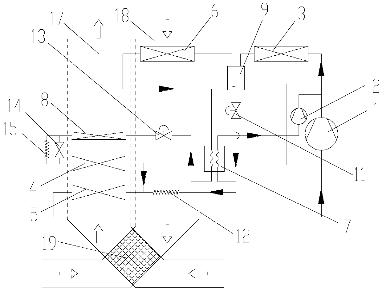
[0058] Such as image 3 As shown, the difference from Embodiment 1 is that the fresh air channel 17 and the exhaust air channel 18 are connected through the total heat exchange device 19, and the total heat exchange device 19 is located on the upstream side of the air flow passing through the dehumidification part, which can further enhance the dehumidification Effect. Such as image 3 As shown, the fresh air enters the total heat exchange device 19 from the air channel, and then enters the fresh air passage 17, the exhaust air enters the total heat exchange device 19, and the exhaust air and the fresh air exchange heat in the total heat exchange device 19, and the outdoor fresh air is pre-heated. While cooling, the energy of the indoor return air is recovered to reduce the energy consumption of the fresh air dehumidification unit.
Embodiment 4
[0060] Such as Figure 4 As shown, the difference from Embodiment 1 is that in this embodiment, a flow control device 20 is provided on the first branch, and the flow control device 20 is arranged in parallel with the third heat exchanger 8. The inlet port of the flow control device 20 The outlet end of the flow control device 20 is connected to the pipeline between the third heat exchanger 8 and the fourth heat exchanger 4 . By providing the flow control device 20 and arranging the flow control device 20 in parallel with the third heat exchanger 8 , the reheat amount can be precisely adjusted by adjusting the flow rate of the flow control device 20 .
PUM
 Abstract
Description
Claims
Application Information
 - R&D Engineer
- R&D Manager
- IP Professional
- Industry Leading Data Capabilities
- Powerful AI technology
- Patent DNA Extraction
Browse by: Latest US Patents, China's latest patents, Technical Efficacy Thesaurus, Application Domain, Technology Topic.
© 2024 PatSnap. All rights reserved.Legal|Privacy policy|Modern Slavery Act Transparency Statement|Sitemap