Passive quick turn-off circuit and turn-off method for airborne bus bar contactor

A technology for shutting off circuits and contactors, applied in circuit devices, emergency protection circuit devices, protection against under-voltage or no-voltage, etc., can solve the problems of increased volume, weight, increased electromagnetic protection, complicated circuits, etc. Achieving the effect of simple circuit and improved reliability

Active Publication Date: 2020-06-05
汉中一零一航空电子设备有限公司
View PDF7 Cites 0 Cited by
  • Summary
  • Abstract
  • Description
  • Claims
  • Application Information

AI Technical Summary

Problems solved by technology

In this way, it is necessary to increase the power conversion circuit, and the corresponding peak surge protection circuit, energy storage circuit, filter circuit, etc., resulting in complex circuits, reduced reliability, and increased volume and weight;
[0009]2) The electromagnetic environment on board is comple

Method used


Image

  • Passive quick turn-off circuit and turn-off method for airborne bus bar contactor
  • Passive quick turn-off circuit and turn-off method for airborne bus bar contactor

Examples


Embodiment Construction

[0024] The present invention is further described below in conjunction with accompanying drawing:

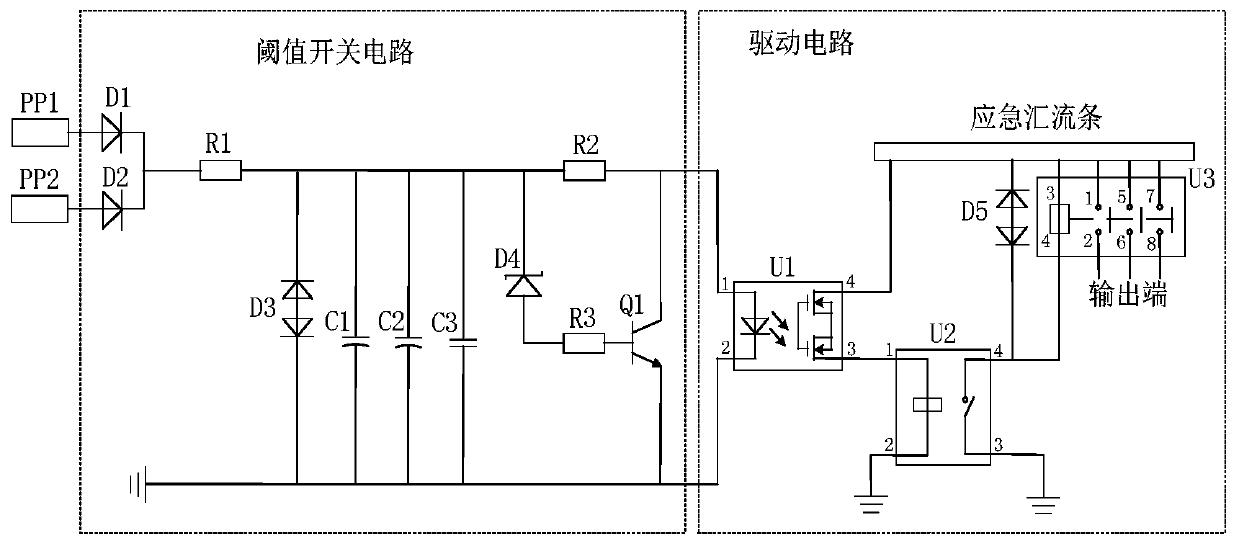
[0025] see figure 1 and figure 2 , an airborne bus bar contactor passive rapid shutdown circuit, including a threshold switch circuit and a drive circuit; the threshold switch circuit is connected to the drive circuit, and the threshold switch circuit receives a voltage for switching the bus bar under the control of the threshold switch circuit The contactor shuts off quickly.

[0026] The threshold switch circuit includes diode D1, diode D2, current limiting resistor R1, resistor R3, TVS tube D3, voltage regulator tube D4, power resistor R2, capacitor C1, capacitor C2, capacitor C3 and transistor Q1; one end of diode D1 and diode D2 Connect the voltage respectively, the other end is connected to the current limiting resistor R1, the current limiting resistor R1 is connected to the TVS tube, and the TVS tube is grounded; the capacitor C1, the capacitor C2, the capacitor C3 and t


PUM


Abstract

The invention relates to a passive quick turn-off circuit and turn-off method for an airborne bus bar contactor. The passive quick turn-off circuit comprises a threshold switch circuit and a driving circuit, and the threshold switch circuit is connected with the driving circuit, receives the voltage and is used for quickly switching off the bus bar contactor under the control of the threshold switch circuit. The framework of the threshold switch circuit and the output drive circuit is used for quickly driving the contactor to act, it is guaranteed that the power conversion time is shorter than50 ms, when the circuit breaks down or is damaged, conduction of the contactor is not affected, the bus bar voltage can normally supply power to a rear-stage load, and the reliability of a power supply system is improved.

Description


Claims


Application Information

Patent Timeline
Owner 汉中一零一航空电子设备有限公司
Why Eureka
Try Eureka