Uplink resource unit distribution method and device

A technology of resource unit and allocation method, applied in the field of communication, can solve problems such as waste of resource unit

Pending Publication Date: 2020-06-05
TP-LINK
View PDF5 Cites 2 Cited by
  • Summary
  • Abstract
  • Description
  • Claims
  • Application Information

AI Technical Summary

Problems solved by technology

[0003] However, in the process of implementing the present invention, the inventors found at least the following problems in the prior art: Since the amount of uplink data transmitted by each wireless station is different, when the time-frequency resource used by the wireless station under the pre-allocated resource

Method used


Image

  • Uplink resource unit distribution method and device
  • Uplink resource unit distribution method and device
  • Uplink resource unit distribution method and device

Examples


Embodiment approach

[0119] As another implementation manner, the method for allocating uplink resource units further includes steps S10 to S11:

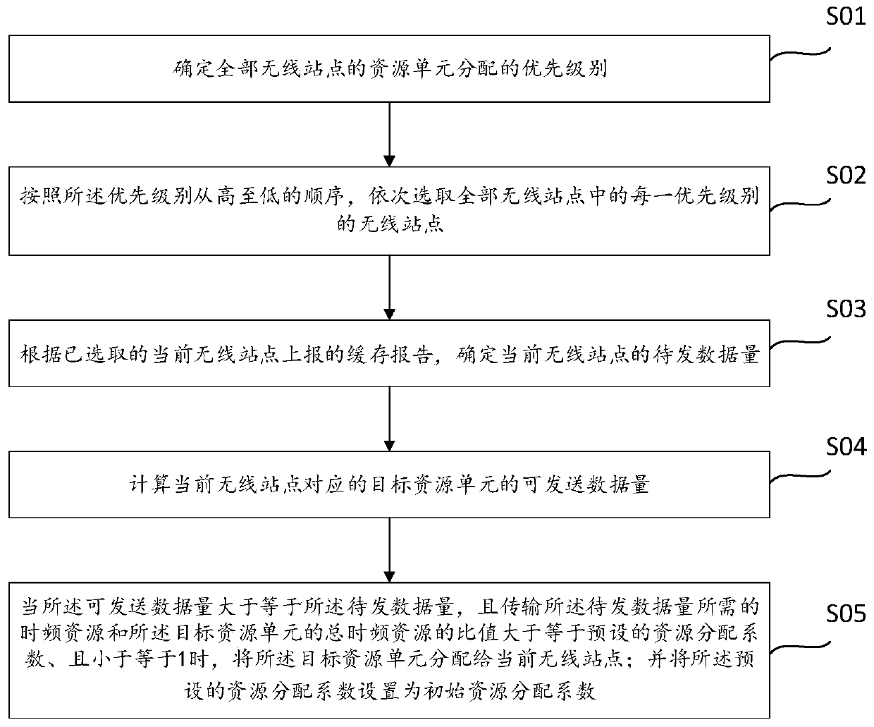
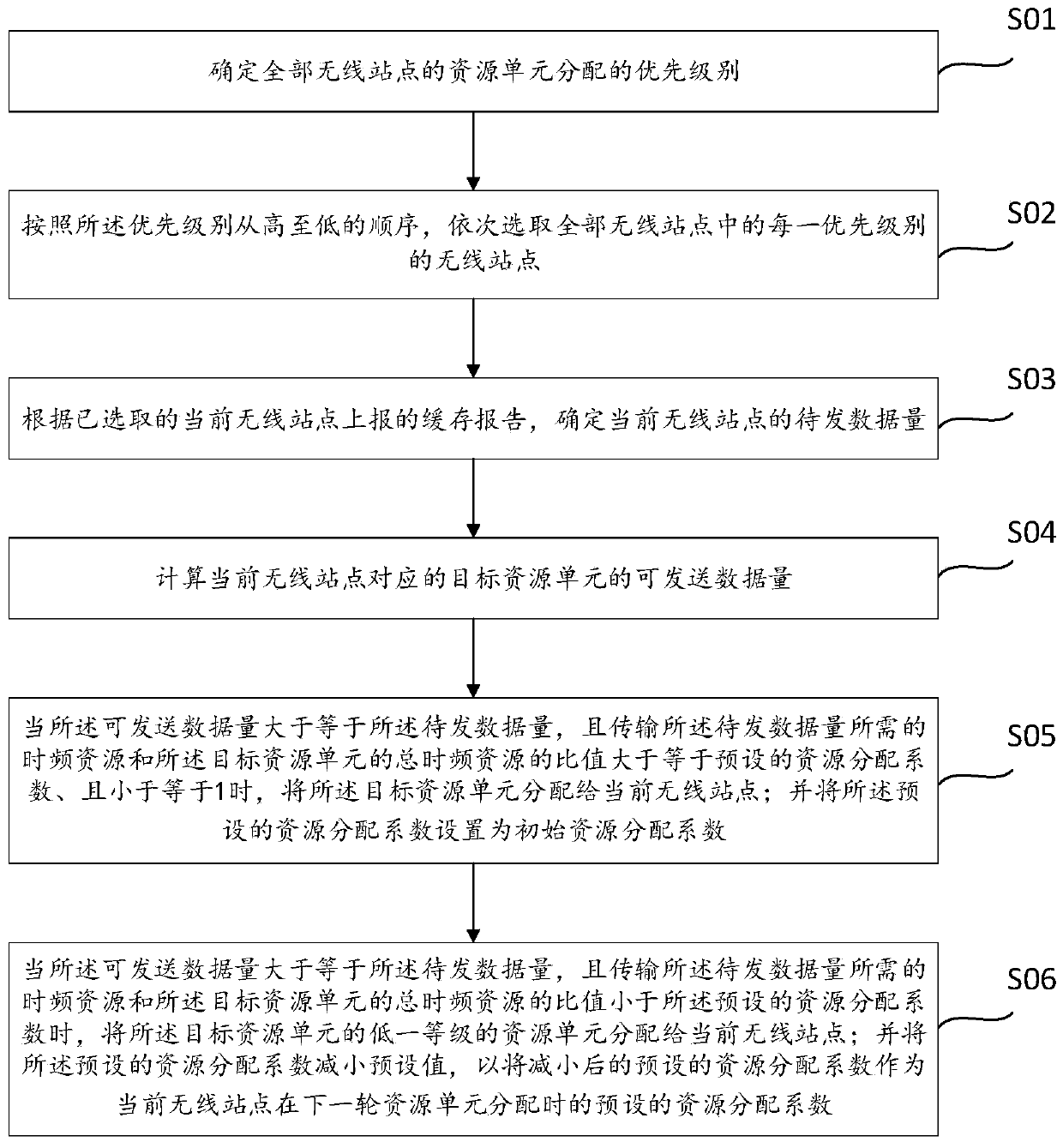
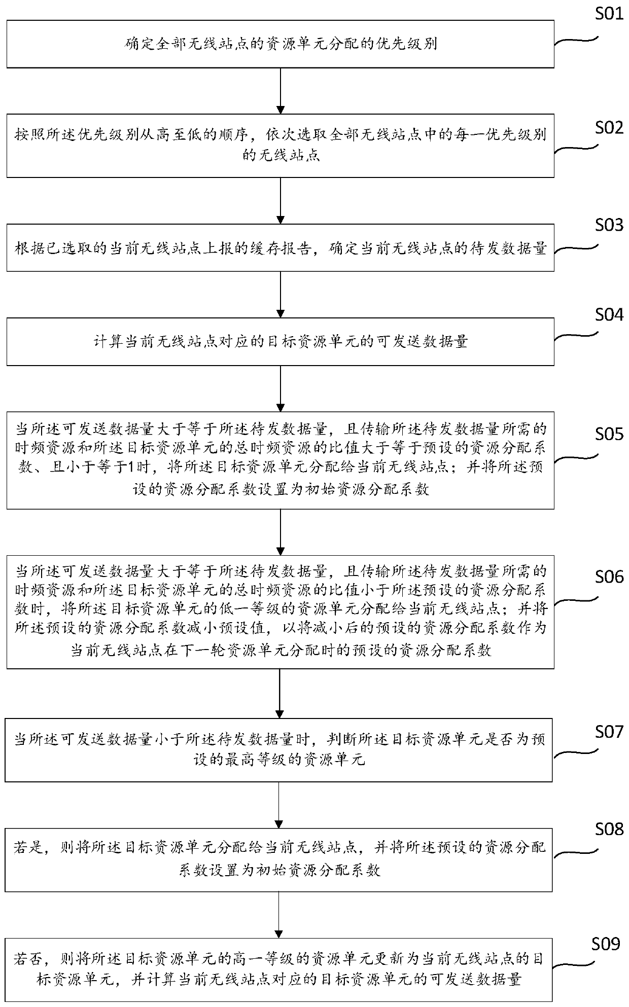
[0120] S10. When the available frequency band cannot be pre-divided into at least one resource unit of a preset level, and the resource unit of the preset level is not the resource unit of the lowest level, allocate the resource units of the lower level of the resource unit of the preset level The resource unit is allocated to the current wireless station; and the preset resource allocation coefficient is reduced by a preset value, so that the reduced preset resource allocation coefficient is used as the preset of the current wireless station in the next round of resource unit allocation The resource allocation coefficient of .

[0121] S11. When the available frequency band cannot be pre-divided into at least one preset level of resource units, and the preset level of resource units is the lowest level of resource units, end the resource unit allocation o


PUM


Abstract

The invention discloses an uplink resource unit distribution method, which comprises the following steps of: sequentially selecting wireless stations of each priority level according to the priority level of each wireless station from high to low, determining the to-be-sent data volume of the selected current wireless station, and calculating the sendable data volume of a target resource unit corresponding to the current wireless station; and when the sendable data volume is greater than or equal to the to-be-sent data volume, and the ratio of the time-frequency resource required for transmitting the to-be-sent data volume to the total time-frequency resource of the target resource unit is greater than or equal to a preset resource allocation coefficient and less than or equal to 1, allocating the target resource unit to the current wireless station. The embodiment of the invention also discloses a corresponding uplink resource unit distribution device. By adopting the embodiment of the invention, the corresponding resource unit is allocated to each wireless station according to the to-be-sent data volume of each wireless station, so that the utilization rate of time-frequency resources is effectively improved, and the resource distribution is optimized.

Description


Claims


Application Information

Patent Timeline
Owner TP-LINK
Why Eureka
Try Eureka