Reactor core neutron flux space-time evolution prediction method and device, medium and equipment

A technology of time-space evolution and prediction method, which is applied in the field of nuclear reactor core operation and safety, to achieve fast calculation speed, short time consumption, and the effect of ensuring core safety

Active Publication Date: 2020-07-10
SOUTH CHINA UNIV OF TECH
View PDF7 Cites 0 Cited by
  • Summary
  • Abstract
  • Description
  • Claims
  • Application Information

AI Technical Summary

Benefits of technology

This patented method allows for accurate detection of changes caused by an accident or other event affecting one's nuclear reactors. It uses techniques such as orthogonality decompositions and matrix expanders to analyze data from multiple sources without compromising their accuracy. By combining these analysis tools together, this system predicts how well certain parts of the fuel assembly behave differently under various conditions over its lifetime. Overall, this approach provides technical benefits including improved reliability and efficiency in detecting accidents involving nuclear power plants.

Problems solved by technology

The technical problem addressed during this patented research is how to improve the ability to monitor and predict the future behavior of an atomic nucleus (N) without requiring continuous measurements over its entire lifetime, which may require long periods before they become fully operational again.

Method used


Image

  • Reactor core neutron flux space-time evolution prediction method and device, medium and equipment
  • Reactor core neutron flux space-time evolution prediction method and device, medium and equipment
  • Reactor core neutron flux space-time evolution prediction method and device, medium and equipment

Examples


Embodiment 1

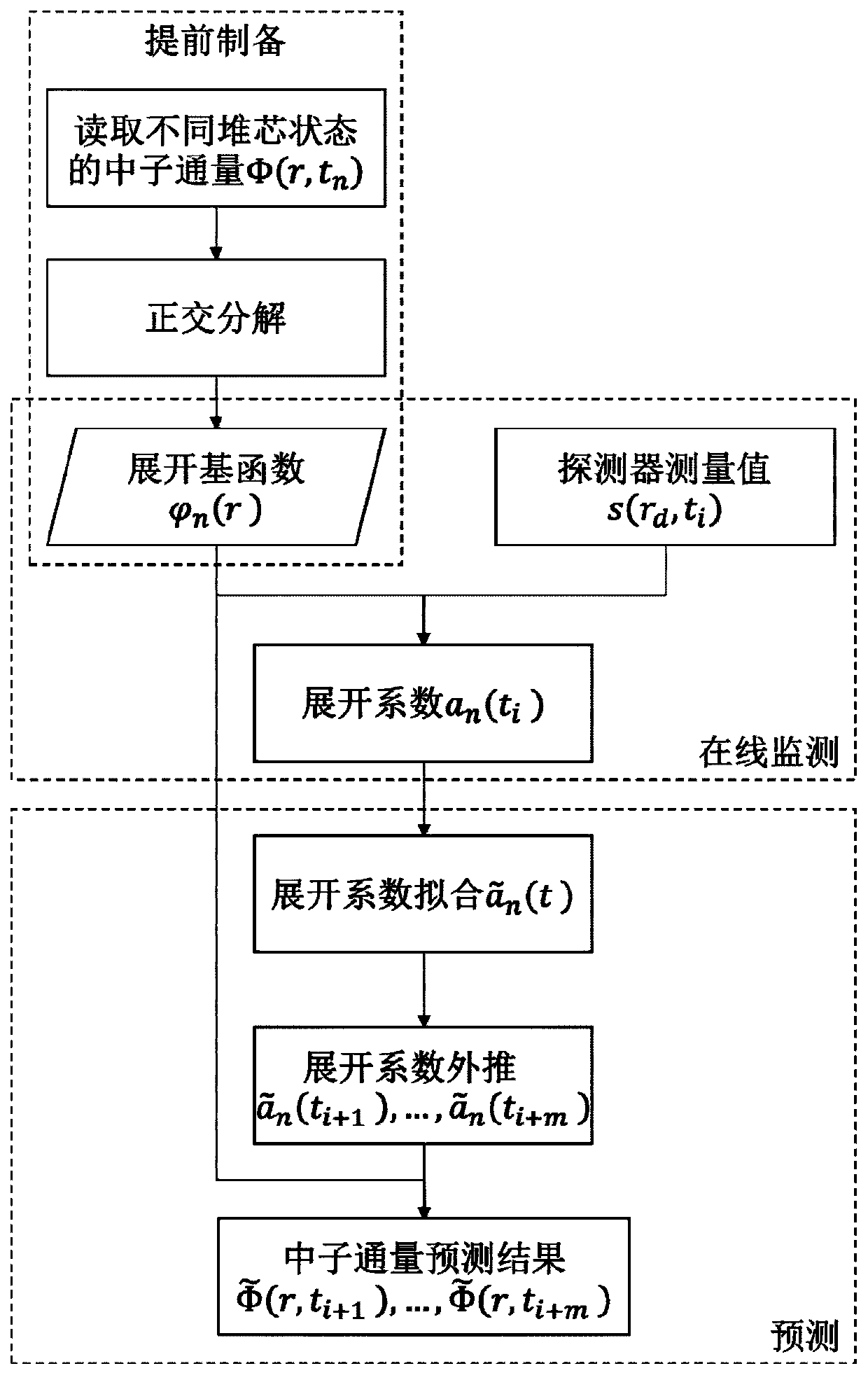
[0040] like figure 1 shown, figure 1 It is a flow chart of the method for predicting the spatiotemporal evolution of core neutron flux according to the present invention, including the following steps:

[0041] S1. Collect the calculated values ​​of neutron flux in different core states Φ(r, t n ), where r represents the spatial position, n=1,2,...,N, where N is the number of different core states; the core states refer to the average burnup, boron concentration, power level, control rod position of the core, corresponding to different time t n;

[0042] S2. Calculate the value Φ(r, t for the N neutron fluxes collected in step S1 n ) is composed of a matrix Orthogonal decomposition is carried out, R is the number of neutron flux space positions, and the orthogonal basis is obtained to obtain the expanded basis function n=1,2,...,N; expand the basis function Prepare and store in advance;

[0043] S3. Collect the measured value s (r) of the detector at the current moment

Embodiment 2

[0063] In order to realize the method for predicting the spatiotemporal evolution of core neutron flux in Embodiment 1, the present embodiment provides a device for predicting the spatiotemporal evolution of core neutron flux, including:

[0064] The data collection module collects the calculated values ​​of neutron flux in different core states Φ(r,t n ), n=1,2,...,N, where N is the number of different core states;

[0065] Expand the base preparation module and calculate the value Φ(r,t for N neutron fluxes n ) to perform orthogonal decomposition to obtain the orthonormal basis to obtain the expanded basis function n=1,2,...,N;

[0066] The real-time data acquisition module collects the measured value s(r) of the detector at the current moment of the core d ,t i ), d=1,2,...,D, D is the number of detectors, t i is the current moment when the core is in actual operation;

[0067] The processing module, according to the current moment of the core detector measurement value

Embodiment 3

[0070] This embodiment provides a storage medium, wherein the storage medium stores a computer program, and when executed by a processor, the computer program causes the processor to perform the prediction of the spatiotemporal evolution of the core neutron flux described in the first embodiment method.


PUM


Abstract

The invention provides a reactor core neutron flux space-time evolution prediction method and device, a medium and equipment, and the method comprises the steps: collecting neutron flux calculation values of different reactor core states; preparing an expansion basis function; acquiring the current detector measurement value of the reactor core; calculating an expansion coefficient at the currentmoment; fitting the expansion coefficient of each order to obtain a change function of the expansion coefficient along with time; extrapolating the expansion coefficient of each order to obtain an expansion coefficient extrapolation value at a subsequent moment; and according to the expansion coefficient extrapolation value and the expansion basis function, performing calculating to obtain a neutron flux prediction result at a subsequent moment. On the basis of the online monitoring results of the reactor core neutron flux at the current moment and the previous moment, the prediction of the reactor core neutron flux at the subsequent moment can be realized, and the space-time evolution process of the reactor core neutron flux is analyzed to ensure the safety of the reactor core of the nuclear reactor.

Description


Claims


Application Information

Patent Timeline
Owner SOUTH CHINA UNIV OF TECH
Why Eureka
Try Eureka