Testing device and testing method capable of rapidly measuring laser receiving sensitivity

A technology for receiving sensitivity and measuring laser light, which is applied in the field of testing devices for rapid measurement of laser receiving sensitivity. It can solve the problems of huge scientific research pressure, unintuitive, invisible laser receiving sensitivity test, etc., and achieve the effect of saving manpower and facilitating testing and analysis.

Pending Publication Date: 2020-07-24
洛阳敦扬科技发展有限公司
View PDF0 Cites 0 Cited by
  • Summary
  • Abstract
  • Description
  • Claims
  • Application Information

AI Technical Summary

Benefits of technology

This new technology allows companies to see how well their products are being used without having to go through any tests themselves. Instead they just have one thing on sale at home instead of going back into school after testing it up again. They use this technology to make sure everything works properly before sending them downstream from manufacturing. By doing these things overall, there's more efficient way to study different aspects of the company's branding materials than traditional methods like measuring distances between points.

Problems solved by technology

This patented technical problem addressed by the current method described in the text relates how accurately detecting small objects can be done with pulsed light (PL) technology due to its high-accuracy and noninvasiveness compared to traditional methods such as radar or LIDAR systems used at longer distances.

Method used


Image

  • Testing device and testing method capable of rapidly measuring laser receiving sensitivity

Examples


Embodiment Construction

[0019] In order to make the purpose, technical solutions and advantages of the embodiments of the present invention clearer, the technical solutions in the embodiments of the present invention will be clearly and completely described below in conjunction with the accompanying drawings in the present invention. Obviously, the described embodiments are the Some embodiments of the invention are not all embodiments. Based on the embodiments of the present invention, all other embodiments obtained by those of ordinary skill in the art without creative efforts fall within the protection scope of the present invention.

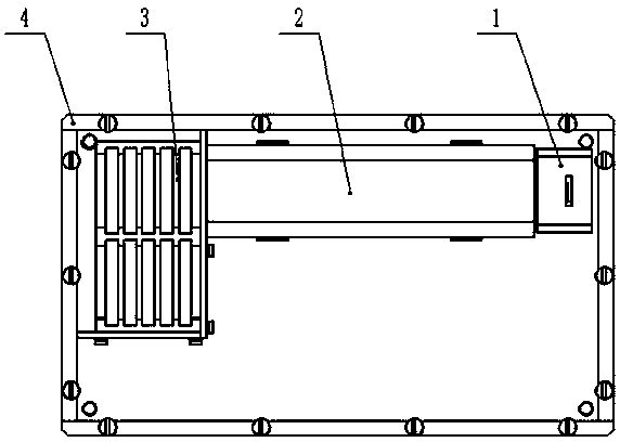
[0020] A test device that can quickly measure the sensitivity of laser receiving. The test device is used to measure and analyze the sensitivity of the product to be tested. The product to be tested in this embodiment can be a receiving module, a receiving antenna and a pulse-type laser rangefinder machine, such as figure 1 As shown, the measurement device includes a tr


PUM


Abstract

The invention provides a testing device capable of rapidly measuring laser receiving sensitivity and a preparation method thereof. The testing device comprises a transmitting module, a transmitting antenna, an attenuation sheet support and a shell; the transmitting module, the transmitting antenna and the attenuation sheet support are all arranged in the shell; the attenuation sheet support is installed at a butt joint port; one end, away from the butt joint port, of the attenuation sheet support is connected with the transmitting module through the transmitting antenna; and a to-be-tested product is placed at the outer side of the butt joint port and is electrically connected with an oscilloscope. According to the invention, sensitivity of the to-be-tested product can be visually analyzed, the performance of the to-be-tested product can be budgeted only through the device without the need of outfield distance measurement and outsourcing test of a distance measuring machine, and specific professional knowledge does not need to be mastered, so that a large amount of manpower and material resources are saved. Meanwhile, test results are visually displayed by means of the oscilloscope, so that scientific researchers can conveniently test and analyze various functions provided by the oscilloscope.

Description


Claims


Application Information

Patent Timeline
Owner 洛阳敦扬科技发展有限公司
Why Eureka
Try Eureka