Trailer
A technology of trailers and trailer frames, which is applied in the field of trailers, can solve problems such as the need to improve safety performance, increase the cost of materials, and shorten the service life, and achieve the effects of improving patency and convenience, fast folding and unfolding, and simple structure
- Summary
- Abstract
- Description
- Claims
- Application Information
AI Technical Summary
Benefits of technology
Problems solved by technology
Method used
Image

Examples
Embodiment 1
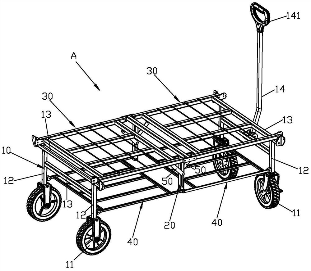
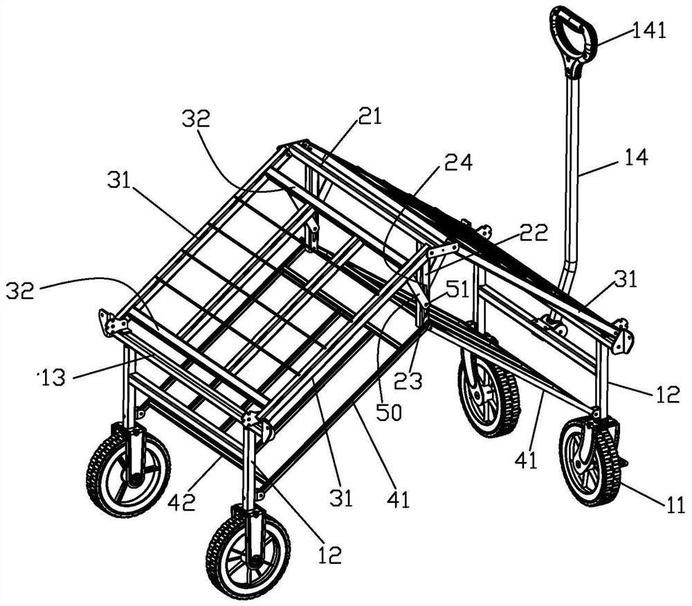
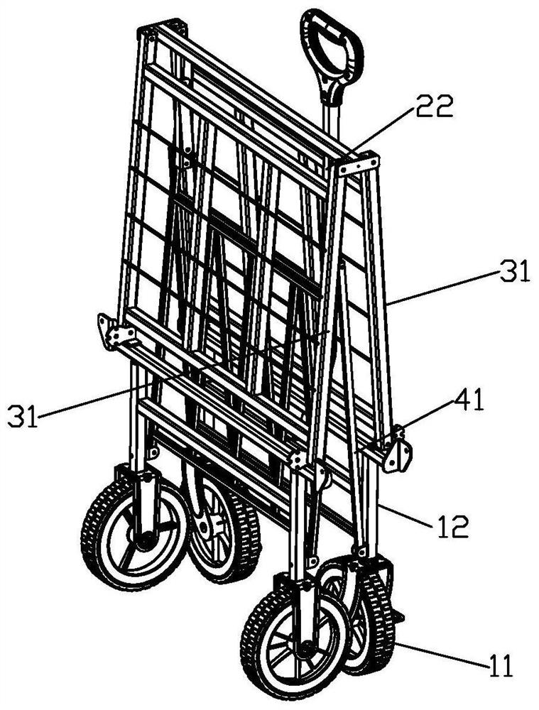
[0051] trailer, see Figures 1 to 6, including a trailer frame A and a synchronous linkage mechanism, the trailer frame A includes two vertical frames 10 arranged front and rear and a middle frame 20, and wheels 11 are mounted under the vertical frame 10. The two vertical frames 10 are all rotatably mounted with a shelf 30 and a link part 40, and the shelf 30 and the link part 40 of the two vertical frames 10 are all rotatably mounted on the middle frame 20, and the two vertical Frame 10, two racks 30, an intermediate frame 20 and two link parts 40 cooperate to form four-bar linkages A1 and A2 of two shared intermediate frames 20; The first ends of the linkages 50 are respectively rotatably attached to the racks 30 of the two stands 10, and the second ends of the two linkages 50 are movably connected to the middle frame 20 and can move up and down synchronously along the middle frame 20. The activity drives the two linkages 50 to move synchronously, and drives the two racks 30 t
Embodiment 2
[0057] It differs from the previous example in that: Please refer to Figure 7 to Figure 10 , the limit mechanism connects the third cross bar 21 of the intermediate frame 20 and the first main beam 31 of the shelf 30 to limit the four-bar linkage mechanism to be in the unfolded state. The position-limiting mechanism includes a lug 24 fixed at the end of the third crossbar 21, and the upper end surface of the lug 24 constitutes an upwardly arranged limiting surface; the rotation of the first main beam 31 and the third crossbar 21 The axis is higher than the limiting surface, and the four-bar linkages A1 and A2 are in an unfolded state when the end of the first main beam 31 leans against the limiting surface.
Embodiment 3
[0059] It differs from the previous example in that: Please refer to Figure 11 to Figure 22 , the trailer frame A is equipped with a fence frame, which includes two side fences 60 and two end fences 70 that can be respectively rotatably attached to the two vertical frames 10, the two side fences 60 and the two end fences The frame 70 can cooperate to form the above-mentioned enclosure frame.
[0060] The end stop 70 can be rotatably attached to the first cross bar 13 on the upper side of the stand 10, so that the end stop 70 can rotate relative to the stand 10, and the end stop 70 can be positioned at the upright state and the horizontal position through the rotation. state and sagging state, the end block 70 and the stand 10 are provided with a second locking mechanism, through the second locking mechanism at least the end block 70 and the stand 10 can be locked to maintain the upright state and the horizontal state . The second locking mechanism is such as a latch, snap-in,
PUM
 Abstract
Description
Claims
Application Information
 - R&D Engineer
- R&D Manager
- IP Professional
- Industry Leading Data Capabilities
- Powerful AI technology
- Patent DNA Extraction
Browse by: Latest US Patents, China's latest patents, Technical Efficacy Thesaurus, Application Domain, Technology Topic.
© 2024 PatSnap. All rights reserved.Legal|Privacy policy|Modern Slavery Act Transparency Statement|Sitemap