Direction finding method and system based on radio frequency analog receiving system

A receiving system and radio frequency technology, applied in direction finders using radio waves, orientators for determining directions, radio wave measurement systems, etc., can solve the problem of unbalanced signal strength of input phase detectors, insufficient application of antennas, and insufficient accuracy Advanced problems, to avoid input signal amplitude imbalance, avoid logical judgment and other operations, and improve the effect of direction finding accuracy

Active Publication Date: 2020-09-22
SOUTHWEST CHINA RES INST OF ELECTRONICS EQUIP
View PDF18 Cites 1 Cited by
  • Summary
  • Abstract
  • Description
  • Claims
  • Application Information

AI Technical Summary

Benefits of technology

The invention provides an improved method for accurately determining directions by combining multiple signals from different sources into one waveform without any issues caused by differences or dispersion that can occur when trying to combine them together. This results in more accurate measurements compared to previous methods such as time-consuming calculations or complicated algorithms.

Problems solved by technology

Technologies described in this patents involve various techniques related to achieving accurate orientation determination from signals obtained through wireless communication systems like space phones or satellites. These include time delay measurements, frequency analysis, polarization matching algorithms, coherence function calculations, waveform inverse scattering, and advanced imageously reconstructable arrays. While these technics aim towards increasing precision and reducing complexity, they still face challenges due to factors including limited reception sensitivity and unstable ground line response caused by multipath distortion.

Method used


Image

  • Direction finding method and system based on radio frequency analog receiving system
  • Direction finding method and system based on radio frequency analog receiving system
  • Direction finding method and system based on radio frequency analog receiving system

Examples


Embodiment Construction

[0059] The present invention will be further described below in conjunction with the accompanying drawings.

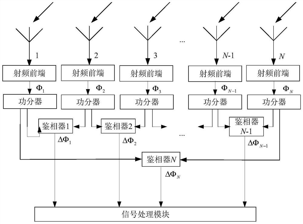
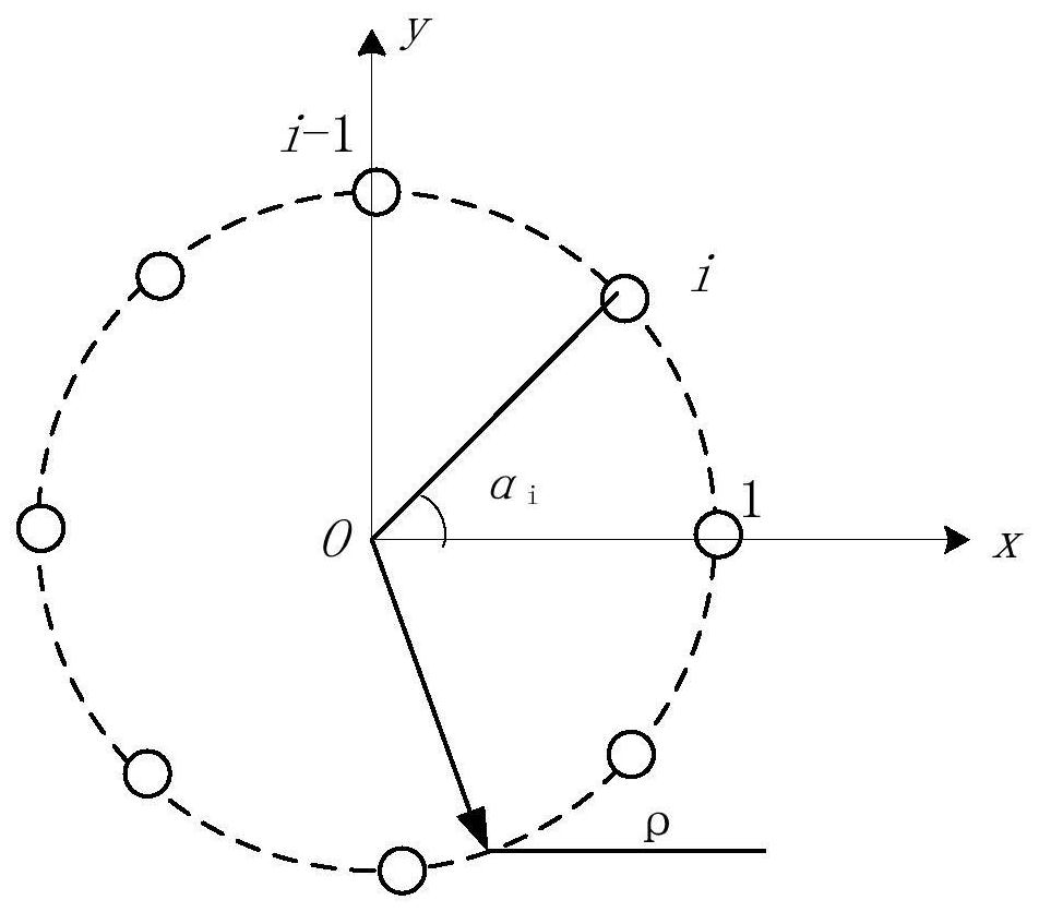
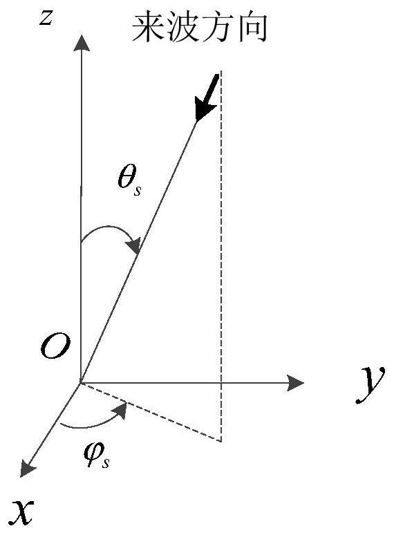
[0060] The present invention provides a two-dimensional incident angle measurement method with simple implementation and high precision, such as figure 1 The radio frequency analog receiving system shown, its main function is to convert space electromagnetic wave into phase difference. After the signal is received by the antenna, it is amplified and filtered by the RF front-end, and then enters into a power splitter. 1 ; The phase difference between the third antenna and the second antenna is recorded as ΔΦ 2 ; and so on until the Nth antenna and the N-1th antenna phase detection, record the phase difference as ΔΦ N-1 . Phase detection between the 1st antenna and the Nth antenna, record the phase difference as ΔΦ N . combine figure 1 The wiring relationship shown, the phase difference output is

[0061]

[0062] Φ i Indicates the voltage phase of the i-th anten


PUM


Abstract

The invention provides a direction finding method based on a radio frequency analog receiving system. The method comprises steps of obtaining the phase difference between each path of antenna and an adjacent antenna through a phase discriminator for an N-element uniform circular array antenna, and recording the phase difference as the phase difference of the phase discriminator; recording the phase difference of each phase discriminator as an initial phase difference when an incoming wave enters the circular array antenna at an elevation angle of 0 degree; constructing a plurality of phase discriminators corresponding to each phase discriminator; according to an elevation angle and an azimuth angle, k is the number of iterations, and calculating the theoretical phase difference of each phase discriminator; introducing a vector X and a direction vector G, and calculating an elevation angle and an azimuth angle of a two-dimensional incident angle of iteration times k+1 in combination with the constructed complex number, calculating the difference between the two-dimensional incident angle with the iteration frequency of k+1 and the iteration frequency of k, comparing the two-dimensional incident angle with a threshold value, and entering an output elevation angle and an azimuth angle when the two-dimensional incident angle is smaller than the threshold value, otherwise, adding 1to the value of k, and calculating the theoretical phase difference. The method is advantaged in that problems of logic judgment and other operations, phase ambiguity and unbalanced amplitude of an input signal of the phase discriminator are avoided, and direction finding precision is improved.

Description


Claims


Application Information

Patent Timeline
Owner SOUTHWEST CHINA RES INST OF ELECTRONICS EQUIP
Why Eureka
Try Eureka