A low phase noise broadband microwave frequency source circuit

A microwave frequency, low phase noise technology, applied in the field of communication, can solve the problems of not being able to output broadband frequency, not using it, not providing actual measurement results, etc.

Active Publication Date: 2018-12-25
SOUTHEAST UNIV
View PDF13 Cites 8 Cited by
  • Summary
  • Abstract
  • Description
  • Claims
  • Application Information

AI Technical Summary

Benefits of technology

This patented technology describes a way to generate high quality signals with less interference from unwanted electrical or magnetic fields that may be generated during operation. It achieves this by creating a signal called a narrow range of frequencies at specific points within it's spectrum. By doing this, researchers can study how different things work together more accurately without affecting each other's performance.

Problems solved by technology

This patented technical problem addressed in these documents relating to high-quality microwaves involves improving their stability during operation due to lower phase noise caused by various factors like temperature variations (PT) and agitation effects from external influences.

Method used


Image

  • A low phase noise broadband microwave frequency source circuit
  • A low phase noise broadband microwave frequency source circuit
  • A low phase noise broadband microwave frequency source circuit

Examples


Embodiment Construction

[0015] The technical solution of the present invention will be further introduced below in combination with specific embodiments.

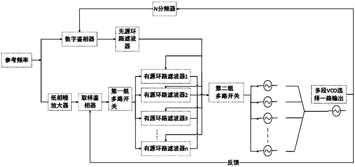
[0016] This specific embodiment discloses a reference frequency input digital phase detector and low phase noise amplifier respectively, such as figure 1 As shown, the output end of the digital phase detector is connected to the input end of the passive loop filter, and the output ends of the passive loop filter are respectively connected to the first ends of multiple active loop filters; the low phase noise amplifier The output end is connected to the input end of the sampling phase detector, the output end of the sampling phase detector is connected to the input end of the first group of multi-way switches, and the output ends of the first group of multi-way switches are respectively connected to the first multiple active loop filters. Two terminals, the third terminals of multiple active loop filters are respectively connected to the input termina


PUM


Abstract

The invention discloses a broadband microwave frequency source circuit with low phase noise. The reference frequency is input into a digital phase detector and a low phase noise amplifier respectively. The output end of the digital phase detector is connected with the input end of a passive loop filter, and the output end of the passive loop filter is connected with the first end of a plurality ofactive loop filters respectively. The output of the low phase noise amplifier is connected to the input of the sampling phase detector. The output of the sampling phase detector is connected to the input of the first set of multiplexers, the output terminals of the first group of multiplexers are respectively connected with the second terminals of a plurality of active loop filters, the third terminals of the plurality of active loop filters are respectively connected with the input terminals of the second group of multiplexers, the output terminals of the second group of multiplexers are respectively connected with a plurality of VCOs, and a plurality of VCOs select one output. The selected VCO output signal is fed back to the sampling phase detector as the system output and fed back tothe digital phase detector through the N divider. The invention realizes the effects of wide frequency band and low phase noise.

Description


Claims


Application Information

Patent Timeline
Owner SOUTHEAST UNIV
Why Eureka
Try Eureka