Rotary table equipment control method, mobile terminal, rotary table equipment and wireless network system

A device control and mobile terminal technology, applied in the network field, can solve the problem of high implementation cost, achieve the effect of improving stability and optimizing signal coverage

Pending Publication Date: 2020-10-16
TP-LINK
View PDF0 Cites 0 Cited by
  • Summary
  • Abstract
  • Description
  • Claims
  • Application Information

AI Technical Summary

Problems solved by technology

[0004] In view of this, the embodiment of the present application provides a turntable device control method, a mobile terminal, a turntable device,

Method used


Image

  • Rotary table equipment control method, mobile terminal, rotary table equipment and wireless network system
  • Rotary table equipment control method, mobile terminal, rotary table equipment and wireless network system
  • Rotary table equipment control method, mobile terminal, rotary table equipment and wireless network system

Examples


Embodiment Construction

[0034] In order to make the purpose, technical solution and advantages of the present application clearer, the present application will be further described in detail below in conjunction with the accompanying drawings and embodiments. It should be understood that the specific embodiments described here are only used to explain the present application, and are not intended to limit the present application.

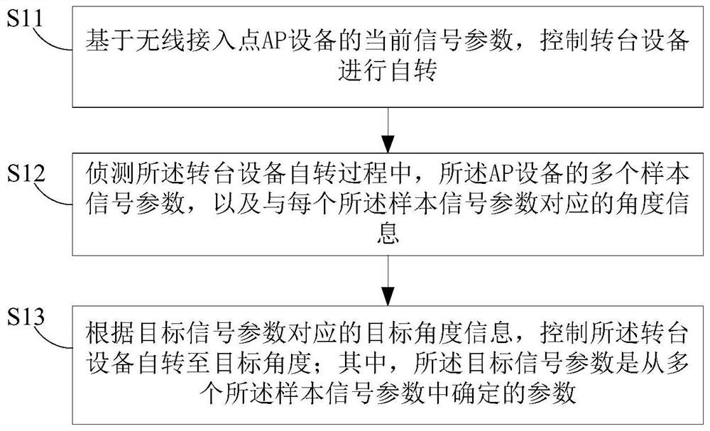
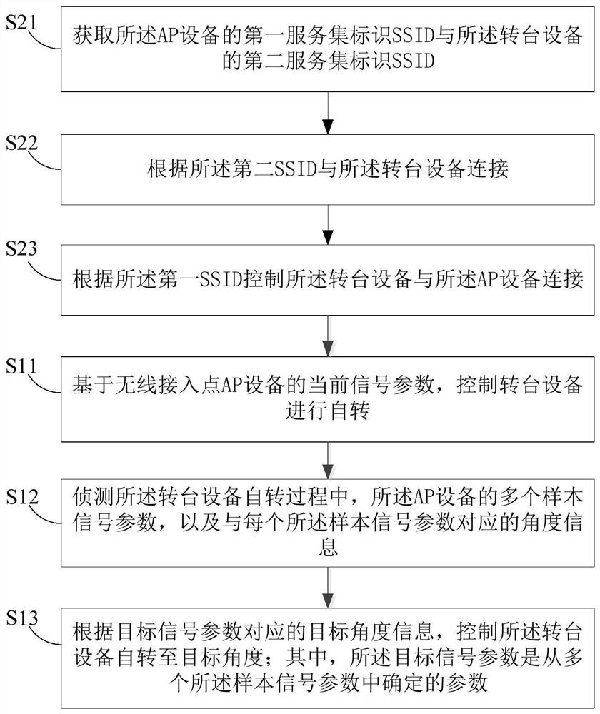
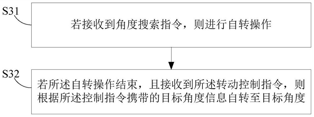
[0035] The turntable device control method involved in the embodiment of the present application includes two aspects. The turntable device control method in the first aspect can be executed by a control device or terminal (hereinafter referred to as "mobile terminal"); the turntable device control method in the second aspect can be performed by The controlled device (hereinafter referred to as "turntable device") executes.

[0036] The control method for the turntable device involved in the embodiment of the present application is suitable for adjusting the angle of the AP d


PUM


Abstract

The present invention is suitable for the technical field of networks. The invention provides a rotary table equipment control method, a mobile terminal, rotary table equipment and a wireless networksystem. The rotary table equipment control method comprises the steps of: controlling the rotary table equipment to rotate on the basis of the current signal parameters of the AP equipment arranged onthe rotary table equipment; meanwhile, in the rotating process of the rotary table equipment, enabling the mobile terminal to detect a plurality of sample signal parameters of the AP equipment and angle information corresponding to each sample signal parameter, and controlling the rotary table equipment to autorotate to a target angle according to the target angle information of the target signalparameters determined from the plurality of sample signal parameters so as to adjust the AP equipment to be a better angle. According to the invention, the signal coverage range of the AP equipment is optimized and the stability of data transmission is improved under the condition of not increasing the implementation cost of the AP equipment and the like.

Description


Claims


Application Information

Patent Timeline
Owner TP-LINK
Why Eureka
Try Eureka