Circulating ventilation device for purifying air in compartment

An internal air and ventilation device technology, applied in parts of pumping devices for elastic fluids, pump devices, vehicle parts, etc., can solve problems such as sensory discomfort, inability to open car windows, increased bacteria, disease transmission, etc.

Pending Publication Date: 2020-10-20
郭发有
View PDF0 Cites 4 Cited by
  • Summary
  • Abstract
  • Description
  • Claims
  • Application Information

AI Technical Summary

Problems solved by technology

[0003] For buses, the common method of ventilation is to open the windows. However, with the increase of air-conditioned vehicles, the windows of many buses are installed in a fully closed manner. In the season when the air conditioner is not turned on, the windows cannot be opened.

Method used


Image

  • Circulating ventilation device for purifying air in compartment
  • Circulating ventilation device for purifying air in compartment
  • Circulating ventilation device for purifying air in compartment

Examples


Embodiment 1

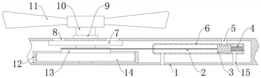
[0024] refer to Figure 1-3 , a circulation ventilation device used for air purification inside the compartment, comprising a compartment wall 1, a hollow groove is opened in the compartment wall 1, and a rotating shaft 10 is installed on the upper surface of the compartment wall 1 through a stopper 9, and the stopper 9 It is a ball bearing, the upper end of the rotating shaft 10 is equipped with a circulation fan 11, the lower end of the rotating shaft 10 runs through the top wall of the hollow groove and extends into the hollow groove, and the middle part of the hollow groove is fixedly installed with a limit cylinder 12, and a disk is arranged inside the limit cylinder 12. Spring 14, one end of the coil spring 14 close to the limit tube 12 is fixedly connected with the inner wall of the limit tube 12, the end of the coil spring 14 away from the limit tube 12 is fixedly connected with a rotating plate 13, and the lower end of the rotating shaft 10 is connected to the rotating pl

Embodiment 2

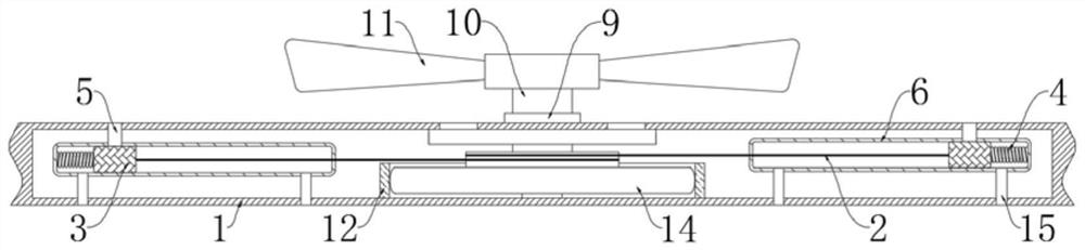
[0037] refer to Figure 4 The difference between this embodiment and Embodiment 1 is that: the lower end of the rotating shaft 10 is fixedly connected with a circular plate 20, and a magnetic block is arranged inside the circular plate 20, and a convex groove 21 is opened on the rotary plate 13, and the circular plate 20 is located on the convex In the shaped groove 21, and against the convex groove 21, the bottom of the convex groove 21 is embedded with a permanent magnet plate 22, and the magnetic poles of the magnetic block and the permanent magnet plate 22 are facing oppositely;

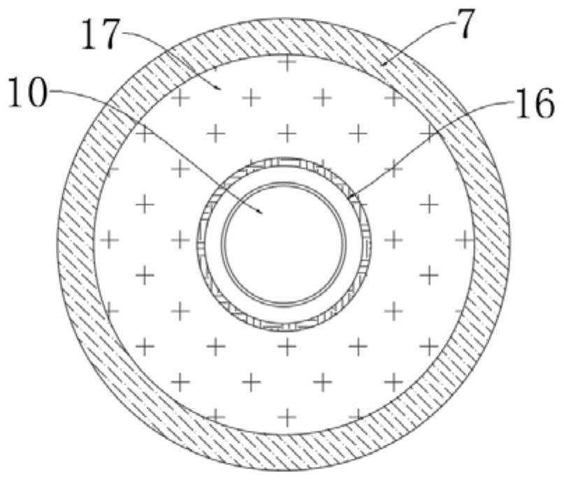
[0038] The circulation fan 11 includes a mounting plate 18. An annular groove is formed in the mounting plate 18, and an expansion member 17 is disposed in the annular groove. A plurality of drainage grooves 19 communicating with the annular groove are formed on the mounting plate 18.

[0039] When the present embodiment is used, the stopper 9 is no longer a bearing, but a circular ring embedded wit


PUM


Abstract

The invention discloses a circulating ventilation device for purifying air in a compartment, which comprises a compartment wall, wherein a hollow groove is formed in the compartment wall; a rotating shaft is rotationally mounted on the upper surface of the compartment wall through a limiting piece; a circulating fan is mounted at the upper end of the rotating shaft; the lower end of the rotating shaft penetrates through the top wall of the hollow groove and extends into the hollow groove; a limiting cylinder is fixedly installed in the middle of the hollow groove; a coil spring is arranged inthe limiting cylinder; the end, which is close to the limiting cylinder, of the coil spring is fixedly connected with the inner wall of the limiting cylinder; a rotating plate is fixedly connected tothe end, which is away from the limiting cylinder, of the coil spring; the lower end of the rotating shaft is rotationally connected with the rotating plate; and at least one ventilation mechanism isarranged in the hollow groove. According to the invention, a sealing block can be driven to move along a specific path by means of airflow generated when a vehicle runs, so that external fresh air continuously enters the compartment, gas in the compartment is gradually replaced, and the purpose of purifying air is achieved.

Description


Claims


Application Information

Patent Timeline
Owner 郭发有
Why Eureka
Try Eureka