Laser spot welding machine and large-database-based spot welding method

A laser spot welding and spot welding technology, which is applied in laser welding equipment, welding equipment, metal processing equipment, etc., can solve the problems of low processing efficiency, low economic benefits, cumbersome operation, etc., to improve processing efficiency and reduce the amount of calculation , the effect of improving work efficiency

Inactive Publication Date: 2020-10-30
韶关市欧姆机电设备有限公司
View PDF0 Cites 0 Cited by
  • Summary
  • Abstract
  • Description
  • Claims
  • Application Information

AI Technical Summary

Problems solved by technology

[0004] To this end, the embodiment of the present invention provides a laser spot welding machine and a spot welding method based on a large database, which is provided with a workpiece placement assembly composed of a circulation assembly and several workpiece placement units, and the user can simultaneously use the equipment Workpieces are placed on several workpiece placement units, and several workpieces can be welded successively by circulating components during processing. It does not need manual disassembly and assembly of workpieces during operation, which saves a

Method used


Image

  • Laser spot welding machine and large-database-based spot welding method
  • Laser spot welding machine and large-database-based spot welding method
  • Laser spot welding machine and large-database-based spot welding method

Examples


Embodiment Construction

[0044] The implementation mode of the present invention is illustrated by specific specific examples below, and those who are familiar with this technology can easily understand other advantages and effects of the present invention from the contents disclosed in this description. Obviously, the described embodiments are a part of the present invention. , but not all examples. Based on the embodiments of the present invention, all other embodiments obtained by persons of ordinary skill in the art without making creative efforts belong to the protection scope of the present invention.

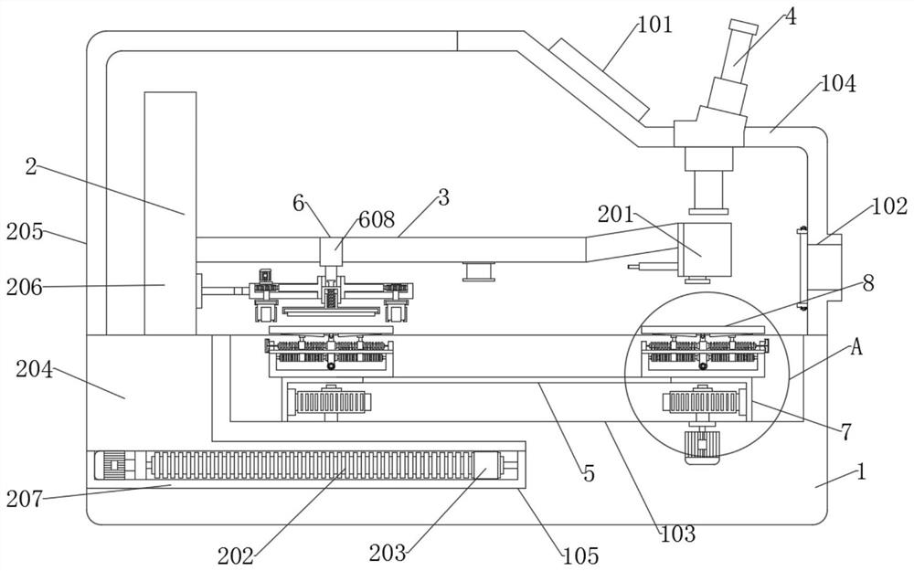
[0045] Such as Figure 1 to Figure 7 As shown, the present invention provides a laser spot welding machine for industrial automation slide rail processing, including a fixed frame 1, a fixed groove 105 is provided at the left end of the fixed frame 1, and a fixed groove 105 is provided in the fixed groove 105. The welding movable assembly 2 can freely slide in the fixed groove 105. When the user ne


PUM


Abstract

The embodiment of the invention discloses a laser spot welding machine. The laser spot welding machine comprises fixing frame. A fixing groove is formed in the left end of the fixing frame. A weldingmoving assembly is arranged within the fixing groove. A shielding cover is arranged at the upper end of the right side of the fixing frame. A placing groove is formed in the upper surface of the fixing frame. A workpiece placement assembly is arranged within the placement groove. The laser spot welding machine is provided with a workpiece placement assembly consisting of a circulation assembly anda number of workpiece placement units. When a user uses the laser spot welding machine, workpieces can be placed on a plurality of workpiece placing units at the same time, and then a plurality of workpieces can be sequentially welded during machining, a large amount of loading time is saved because no manual operation is adopted in workpiece disassembly; and meanwhile, the number of workpieces machined by the laser spot welding machine is large, and even if the number of workpieces needing to be machined is large, simultaneous operation of a plurality of sets of equipment is not needed. Theoperation is simple and convenient, and the working efficiency is also improved.

Description


Claims


Application Information

Patent Timeline
Owner 韶关市欧姆机电设备有限公司
Why Eureka
Try Eureka