Composite barrel thermal switch
A technology of thermal switch and inner cylinder, which is applied in the field of composite cylinder thermal switch for refrigerators, can solve the problems of high thermal conductivity of the thermal switch cylinder, achieve the effects of long thermal conductivity, low thermal conductivity, and increased cooling capacity
- Summary
- Abstract
- Description
- Claims
- Application Information
AI Technical Summary
Benefits of technology
Problems solved by technology
Method used
Image

Examples
Embodiment 1
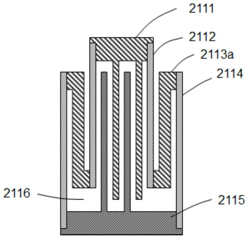
[0030] Such as figure 1 As shown, the thermal switch of the composite cylinder includes an upper flange 2111, a lower flange 2115, and a composite thermal switch cylinder located between the upper and lower flanges. The composite thermal switch cylinder includes an inner cylinder 2112, an outer cylinder 2114 and a first intermediate cylinder 2113a , where the top of the inner cylinder 2112 is connected to the upper flange 2111, the bottom of the outer cylinder 2114 is connected to the lower flange 2115, the first intermediate cylinder 2113a is located between the inner cylinder 2112 and the outer cylinder 2114, the bottom of which is connected to the inner cylinder 2112, and the top is connected to The outer cylinder 2114 forms a closed cavity with a folded section. Among them, the upper flange 2111 and the lower flange 2115 are covered with fins, and the distance between the fins is very close; figure 1 As shown, the upper flange 2111 is provided with downwardly extending fins
Embodiment 2
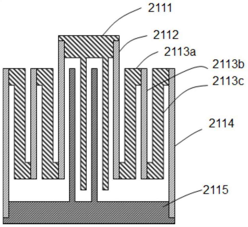
[0034] Such as figure 2 As shown, a composite thermal switch is composed of an upper flange, a lower flange and a composite thermal switch barrel. The composite thermal switch cylinder is composed of an inner cylinder 2112, a first middle cylinder 2113a, a second middle cylinder 2113b, a third middle cylinder 2113c and an outer cylinder 2114 to form a folding structure. All the other are with embodiment 1.
[0035] In this embodiment, the second intermediate cylinder 2113b and the third intermediate cylinder 2113c are added, which have a longer heat conduction length and lower thermal conductivity.
[0036] The number of intermediate cylinders can be set in multiples as required.
[0037] The thermal switch is opened when it is filled with helium, and the fins a and b inside conduct heat through helium, so that heat can be conducted between the upper and lower flanges. After the helium is pumped away, there is a vacuum inside, fin a and fin b cannot conduct heat, and there is
Embodiment 3
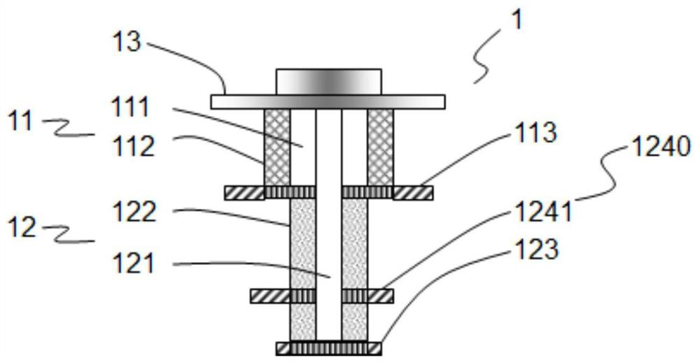
[0041] The composite thermal switch of the present invention is used in a composite refrigerator coupled with a regenerative refrigerator and a magnetic refrigerator, and the structure is as follows Figure 3-5 As shown, it includes a regenerative refrigerator 1 and a first-stage magnetic refrigerator 2 .
[0042] Among them, the regenerative refrigerator 1 is a two-stage 4K pulse tube refrigerator, which is composed of a top flange 13, a first-stage pulse tube subunit 11 and a final-stage pulse tube sub-unit 12, wherein the first-stage pulse tube sub-unit 11 includes a first-stage The pulse tube 111, the first-stage regenerator 112 and the first-stage cold head 113, the final-stage pulse tube subunit 12 includes the final-stage pulse tube 121, the final-stage regenerator 122 and the final-stage cold head 123, and the final-stage heat recovery A residual cold head 1240 is installed on the container 122, and the residual cold head 1240 includes a residual cold head, that is, a fir
PUM
 Abstract
Description
Claims
Application Information
 - R&D Engineer
- R&D Manager
- IP Professional
- Industry Leading Data Capabilities
- Powerful AI technology
- Patent DNA Extraction
Browse by: Latest US Patents, China's latest patents, Technical Efficacy Thesaurus, Application Domain, Technology Topic.
© 2024 PatSnap. All rights reserved.Legal|Privacy policy|Modern Slavery Act Transparency Statement|Sitemap