Operating handle for installing drug dissolving apparatus

A technology for operating handles and drug dissolving devices, which is applied to medical containers, packaging, and packaged foods. It can solve the problems of affecting the sealing of the connection between the operating handle and the filter device, the low service life of the operating handle, and the inconvenience of replacement, so as to facilitate assembly. , Improve the service life and facilitate disassembly and assembly

Pending Publication Date: 2020-11-27
石家庄博普信息科技有限公司
View PDF0 Cites 0 Cited by
  • Summary
  • Abstract
  • Description
  • Claims
  • Application Information

AI Technical Summary

Problems solved by technology

However, it is extremely inconvenient to replace the filter device of the existing dispensing equipment, and the filter devi

Method used


Image

  • Operating handle for installing drug dissolving apparatus
  • Operating handle for installing drug dissolving apparatus
  • Operating handle for installing drug dissolving apparatus

Examples


Embodiment Construction

[0044] Preferred embodiments of the present invention will be described below in conjunction with the accompanying drawings. It should be understood that the preferred embodiments described here are only used to illustrate and explain the present invention, not to limit the present invention.

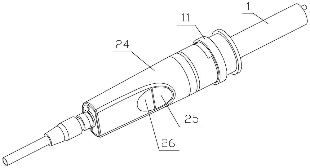
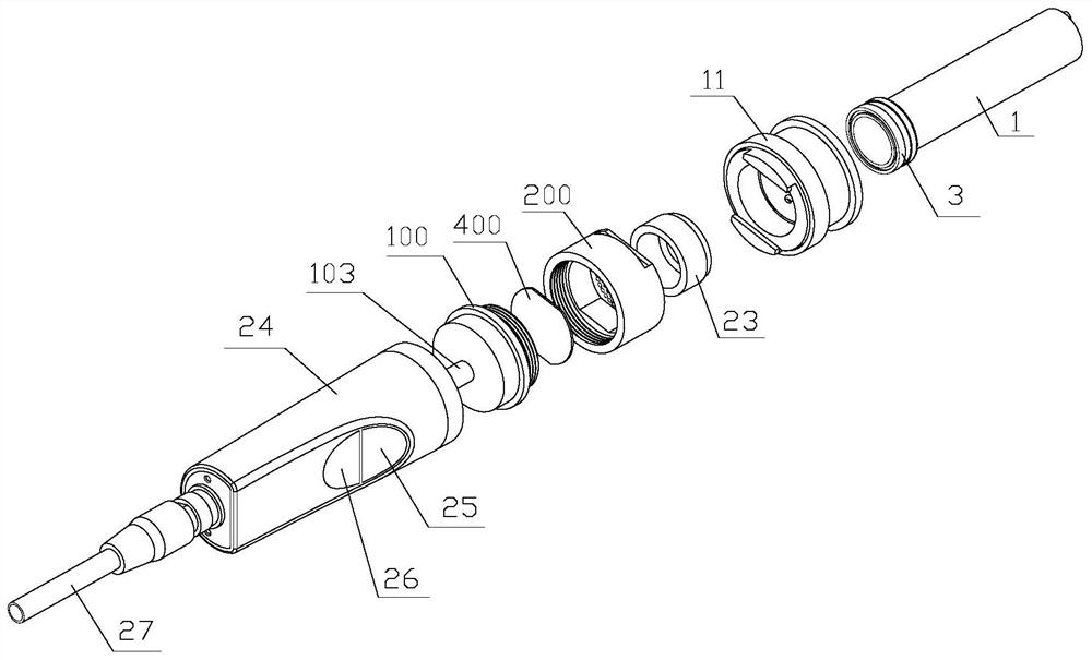
[0045] The invention discloses an operating handle for installing a drug dissolver, such as Figure 1-2 As shown, the handle body 24 is included, the handle body 24 is equipped with an air intake button 25 and an air extraction button 26, and the air intake button 25 and the air extraction button 26 are respectively electrically connected to the PLC, and one end of the handle body 24 is inserted with a trachea 27, The air pipe 27 extends into the handle body 24 and is connected to the air filter installed at the other end of the handle body 24. The end of the air filter away from the handle body 24 is detachably connected with a connector, and the handle body 24 is detachably connected to


PUM


Abstract

The invention discloses an operating handle for installing drug dissolving apparatus. The operating handle comprises a handle body, wherein an air inlet button and an air exhaust button are arranged on the handle body, and are electrically connected with a PLC; an air pipe is inserted into one end of the handle body, and is connected with an air filter installed at the other end of the handle body; a connector is detachably connected to one end, away from the handle body, of the air filter, and the handle body is detachably connected with a syringe body through the connector; and the connectorcomprises a connecting sleeve which is connected with the handle body and in bell and spigot connection with the syringe body, the syringe body is provided with a flange connected with the connectingsleeve, and a limiting and tightening mechanism for tightening the flange is movably arranged on the connecting sleeve. The purposes of facilitating disassembly and assembly, prolonging the service life of the operating handle and preventing reduction of sealing performance of a joint between the operating handle and the filtering device are achieved. The operating handle is applicable to the technical field of drug dispensing equipment.

Description


Claims


Application Information

Patent Timeline
Owner 石家庄博普信息科技有限公司
Why Eureka
Try Eureka