Water quality monitoring circulation tank and water quality monitoring method

A technology for water quality monitoring and flow trough, applied in chemical instruments and methods, cleaning methods and utensils, cleaning methods using liquids, etc. The effect of reducing impact and improving accuracy

Pending Publication Date: 2020-12-04
上海淳业仪表科技有限公司
View PDF4 Cites 2 Cited by
  • Summary
  • Abstract
  • Description
  • Claims
  • Application Information

AI Technical Summary

Benefits of technology

This technology helps keep your equipment running smoothly even with poor or noisy waters that may affect its performance. It uses an automatic cleaner system for better control over any harmful substances found inside it's body.

Problems solved by technology

This patented technical problem addressed in this patents relates to improves the precision and reliability of water-quality monitoring systems that use multiple types of sensing devices with different characteristics (flow tanks) at varying depth levels within a ship's hull during operation.

Method used


Image

  • Water quality monitoring circulation tank and water quality monitoring method
  • Water quality monitoring circulation tank and water quality monitoring method
  • Water quality monitoring circulation tank and water quality monitoring method

Examples


Embodiment Construction

[0029] Exemplary embodiments of the present disclosure are described below with reference to the accompanying drawings. It should be understood that these specific descriptions are only used to teach those skilled in the art how to implement the present disclosure, but are not intended to exhaust all possible ways of the present disclosure, nor are they used to limit the scope of the present disclosure.

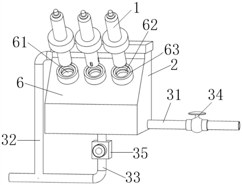
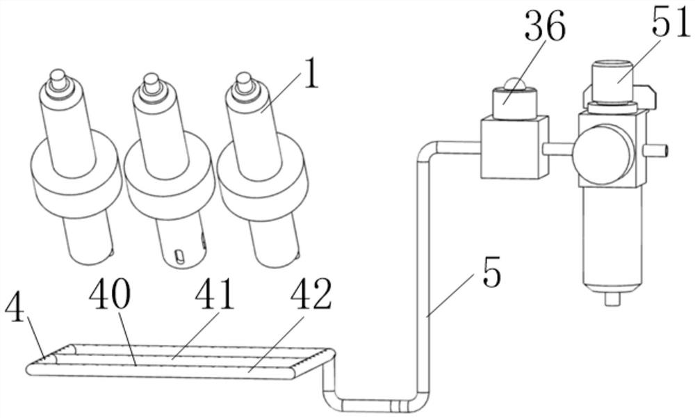
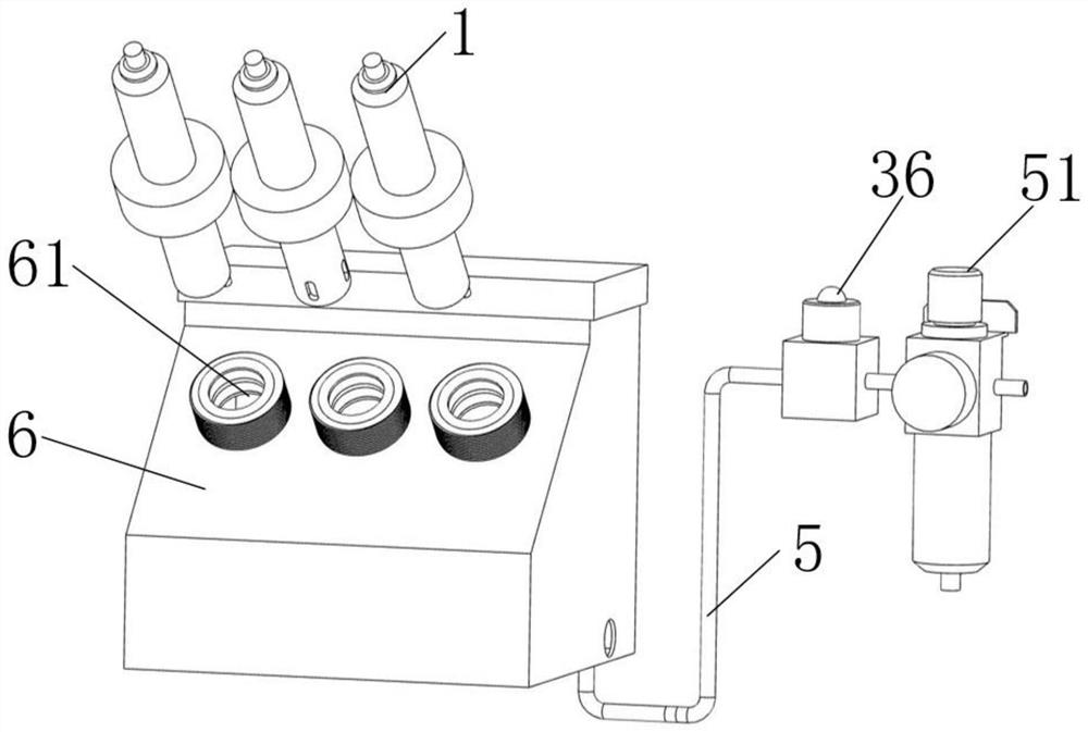
[0030] Such as Figure 1 to Figure 3 As shown, the present disclosure provides a flow tank for water quality monitoring, which may include a water quality monitoring sensor 1 , a box body 2 and a water pipe. The water quality monitoring sensor 1 is installed in the box body 2 , and the probe of the water quality monitoring sensor 1 is located in the box body 2 .

[0031] The water pipe is connected to the box body 2. The water pipe includes a water inlet pipe 31 and an outlet pipe 32. The monitoring water sample enters the box body 2 through the water inlet pipe 31 and flows out


PUM


Abstract

The invention provides a water quality monitoring circulation tank and a water quality monitoring method, wherein the water quality monitoring circulation tank comprises a box body, the box body is used for mounting a water quality monitoring sensor and allowing a monitoring water sample to flow through, the water quality monitoring circulation tank further comprises a cleaning gas pipe, and the cleaning gas pipe is mounted in the box body. The cleaning gas pipe is provided with a gas outlet hole used for releasing compressed air, and the gas outlet hole can be at least aligned with a probe ofthe water quality monitoring sensor. The water quality monitoring circulation tank has a self-cleaning function by arranging the cleaning gas pipe, so that the water quality monitoring sensor is cleaned, the influence of impurities in the monitoring water sample on a measurement result is reduced, and the accuracy of the measurement result is improved.

Description


Claims


Application Information

Patent Timeline
Owner 上海淳业仪表科技有限公司
Why Eureka
Try Eureka