Electric device and switch device thereof

A technology of switchgear and compressed air chamber, which is applied in the field of switchgear and can solve problems such as large operating power

Active Publication Date: 2020-12-04
STATE NUCLEAR ELECTRIC POWER PLANNING DESIGN & RES INST CO LTD +1
View PDF18 Cites 0 Cited by
  • Summary
  • Abstract
  • Description
  • Claims
  • Application Information

AI Technical Summary

Problems solved by technology

If high current switches like general SF 6 Like a circuit breaker, if the main contact and the arc contact are designed to have the same movement characteristics, the mechanism operation work required will be very large

Method used


Image

  • Electric device and switch device thereof
  • Electric device and switch device thereof

Examples


Example Embodiment

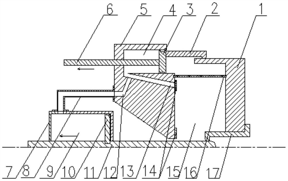
[0027] The invention discloses a switch device to ensure that a large amount of clean and low-temperature gas can be supplemented between thermal expansion chambers or fractures before the current crosses zero. In addition, the present invention also discloses an electrical device having the above-mentioned switch device.

[0028] The technical solutions in the embodiments of the present invention will be clearly and completely described below with reference to the accompanying drawings in the embodiments of the present invention. Obviously, the described embodiments are only a part of the embodiments of the present invention, but not all of the embodiments. Based on the embodiments of the present invention, all other embodiments obtained by those of ordinary skill in the art without creative efforts shall fall within the protection scope of the present invention.

[0029] like figure 1 and figure 2 As shown, the present application discloses a switchgear for breaking large cu


PUM


Abstract

The invention discloses an electric device and a switch device thereof which are used for switching on and switching off a large current. The electric device comprises a thermal expansion chamber, anda moving main contact and a moving arc contact which asynchronously move in the same direction, and further comprise a first air compression chamber and a second air compression chamber. The first air compression chamber is communicated with the thermal expansion chamber, and a first air compression piston in the first air compression chamber is connected with the moving main contact; the secondair compression chamber is communicated with the thermal expansion chamber, and a second air compression piston in the second air compression chamber is connected with the moving arc contact; and theoperation directions of the compressed air of the first air compression piston and the second air compression piston are the same as the opening movement direction of the moving main contact. By adding the second air compression chamber, the second air compression chamber is connected with the moving arc contact, and the compressed air generated in the moving process of the moving arc contact is input into the thermal expansion chamber. Under the condition that the gas in the first gas compression chamber is little or hardly enters the thermal expansion chamber, the clean low-temperature gas in the second gas compression chamber can still be input into the thermal expansion chamber along with the movement of the second gas compression piston, and the arc extinguishing effect of the switchdevice is effectively improved.

Description


Claims


Application Information

Patent Timeline
Owner STATE NUCLEAR ELECTRIC POWER PLANNING DESIGN & RES INST CO LTD
Why Eureka
Try Eureka