Clinical anti-infection isolation device and operation method

An isolation device and infection prevention technology, applied in the field of medical devices, can solve the problems of poor isolation effect, low transport efficiency, and troublesome transport, and achieve the effects of good discharge efficiency, thorough discharge, and easy disassembly and replacement.

Active Publication Date: 2020-12-18
黑龙江省医院
View PDF13 Cites 6 Cited by
  • Summary
  • Abstract
  • Description
  • Claims
  • Application Information

AI Technical Summary

Problems solved by technology

[0002] In the process of admission and transfer of infectious patients, it is necessary to isolate patients to prevent the spread of pathogens and reduce the transmission of pathogens. This requires an isolation device. At present, there is no set of effective equipment to complete the process of patient admission and transfer. Especially in the process of patient admission, the isolation effect is not good, the transfer is more troublesome, and the transfer efficiency is low

Method used


Image

  • Clinical anti-infection isolation device and operation method
  • Clinical anti-infection isolation device and operation method
  • Clinical anti-infection isolation device and operation method

Examples


Example Embodiment

[0028]Hereinafter, the present invention will be further described in detail based on the drawings and embodiments:

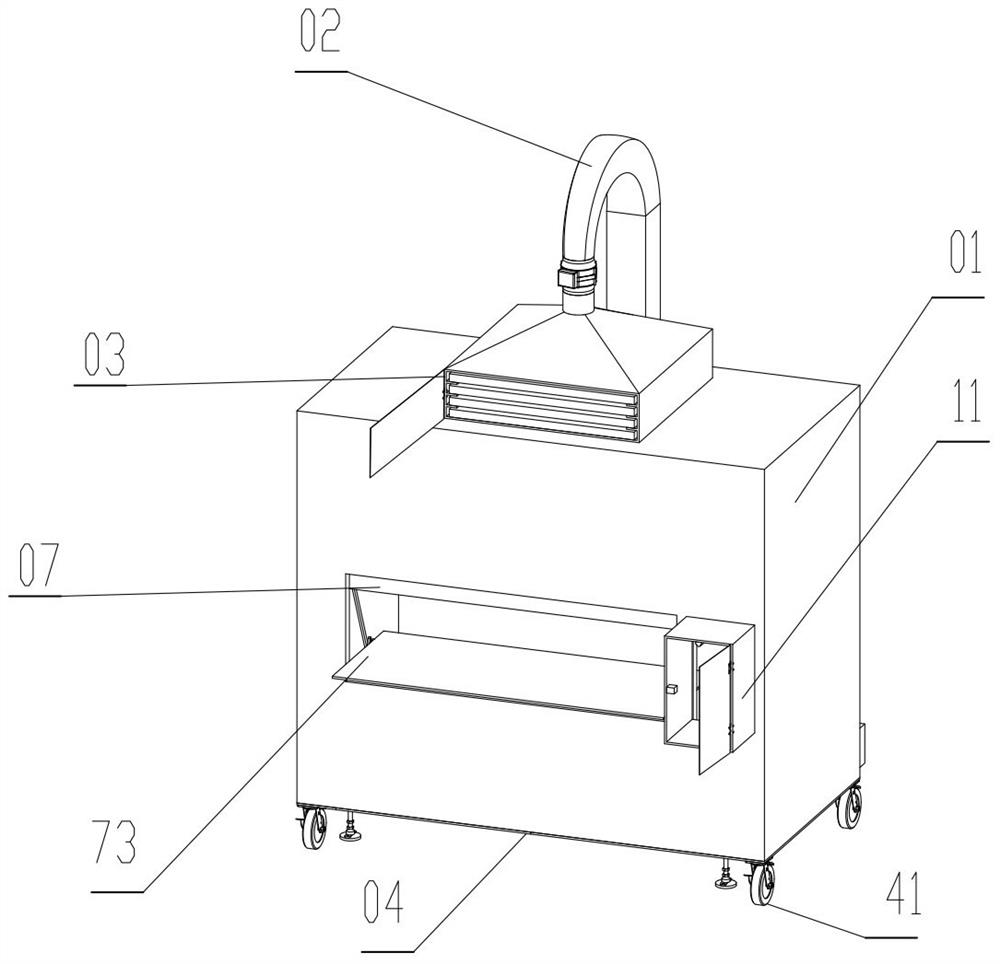
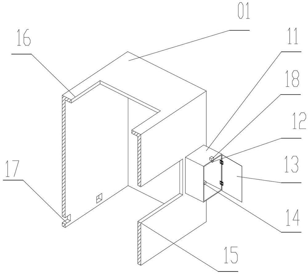
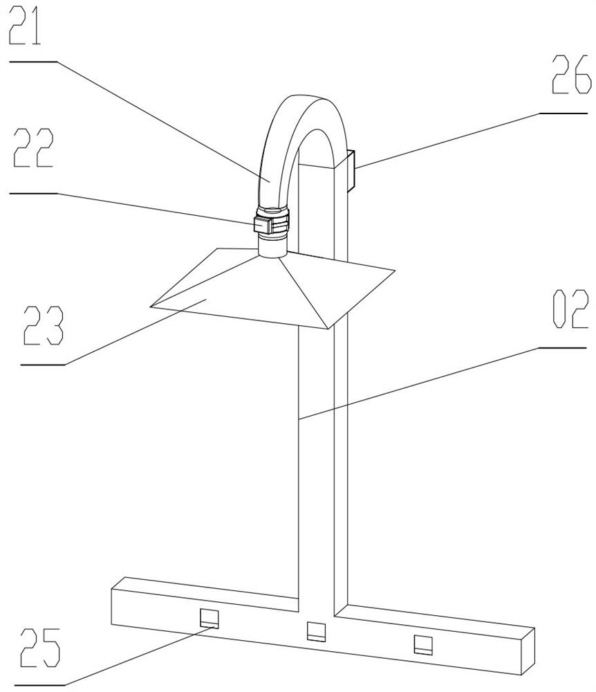
[0029]A clinical anti-infection isolation device, including isolation room 01, air duct 02, filter box 03, bottom plate 04, universal wheels 41, slide rail 06, observation window 07, bed body 73, isolation room 01 has an air inlet 16 on the top, The lower part of the side sealing plate on the left side of the isolation room 01 has three air outlets 17, and the outside of the air outlet 17 is sealed and connected to the air duct 02. The air duct 02 has an air outlet 25. The air outlet 17 corresponds to the air outlet 25. The air duct 02 has a fresh air outlet. 26. The upper part of the air duct 02 is sealed and connected to the elbow 21, the elbow 21 is sealed to the fan 22, and the fan 22 is sealed to the filter box 03. The filter box 03 has four notches 32. The notch 32 below the primary filter 34 is connected to the medium efficiency filter 35 in a sealed manner, the not


PUM


Abstract

The invention provides a clinical anti-infection isolation device and an operation method. The device comprises an isolation room, an air duct, a filter box, a bottom plate, universal wheels, a sliding rail, an observation window and a bed body, wherein an air inlet is formed in the top of the isolation room; three air outlets are formed in the lower part of a side sealing plate on the left side of the isolation room; the outer sides of the air outlets are hermetically connected with the air duct; the air duct is provided with air ports; the air outlets correspond to the air ports; a fresh airport is formed in the air duct; the upper part of the air duct is hermetically connected with an elbow; the elbow is hermetically connected with a fan; the fan is hermetically connected with the filter box; the filter box is provided with four notches; the notch close to one side of the fan is hermetically connected with a primary filter; the notch below the primary filter is hermetically connected with a medium-efficiency filter; the notch below the medium-efficiency filter is hermetically connected with a high-efficiency filter; the notch below the high-efficiency filter is connected with alamp holder; and the lamp holder is fixedly connected with an ultraviolet lamp.

Description


Claims


Application Information

Patent Timeline
Owner 黑龙江省医院
Why Eureka
Try Eureka