Loudspeaker box

A loudspeaker box, rear acoustic cavity technology, applied in the transducer shell/cabinet/stand, frequency/directional characteristic device and other directions, can solve the problems of limited acoustic performance, limit the volume design of the front cavity and the rear cavity, etc., to increase the volume , Improve acoustic performance, easy assembly effect

Pending Publication Date: 2020-12-29
RUISHENG NEW ENERGY DEV CHANGZHOU +1
View PDF0 Cites 0 Cited by
  • Summary
  • Abstract
  • Description
  • Claims
  • Application Information

AI Technical Summary

Problems solved by technology

[0004] However, the front cover and the rear cover of the loudspeaker box in the related art are injection-molded, and the sealing of the sounding unit is realized by means of u

Method used


Image

  • Loudspeaker box
  • Loudspeaker box
  • Loudspeaker box

Examples


Embodiment Construction

[0024] The following will clearly and completely describe the technical solutions in the embodiments of the present invention with reference to the accompanying drawings in the embodiments of the present invention. Obviously, the described embodiments are only some, not all, embodiments of the present invention. Based on the embodiments of the present invention, all other embodiments obtained by persons of ordinary skill in the art without making creative efforts belong to the protection scope of the present invention.

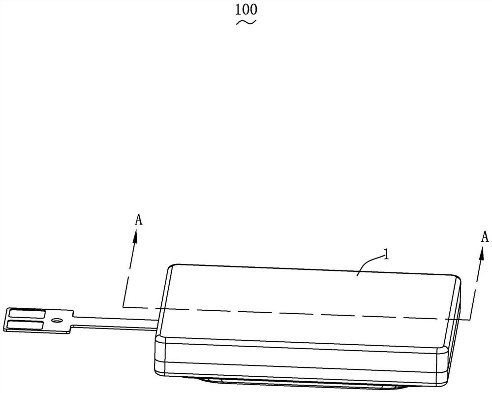
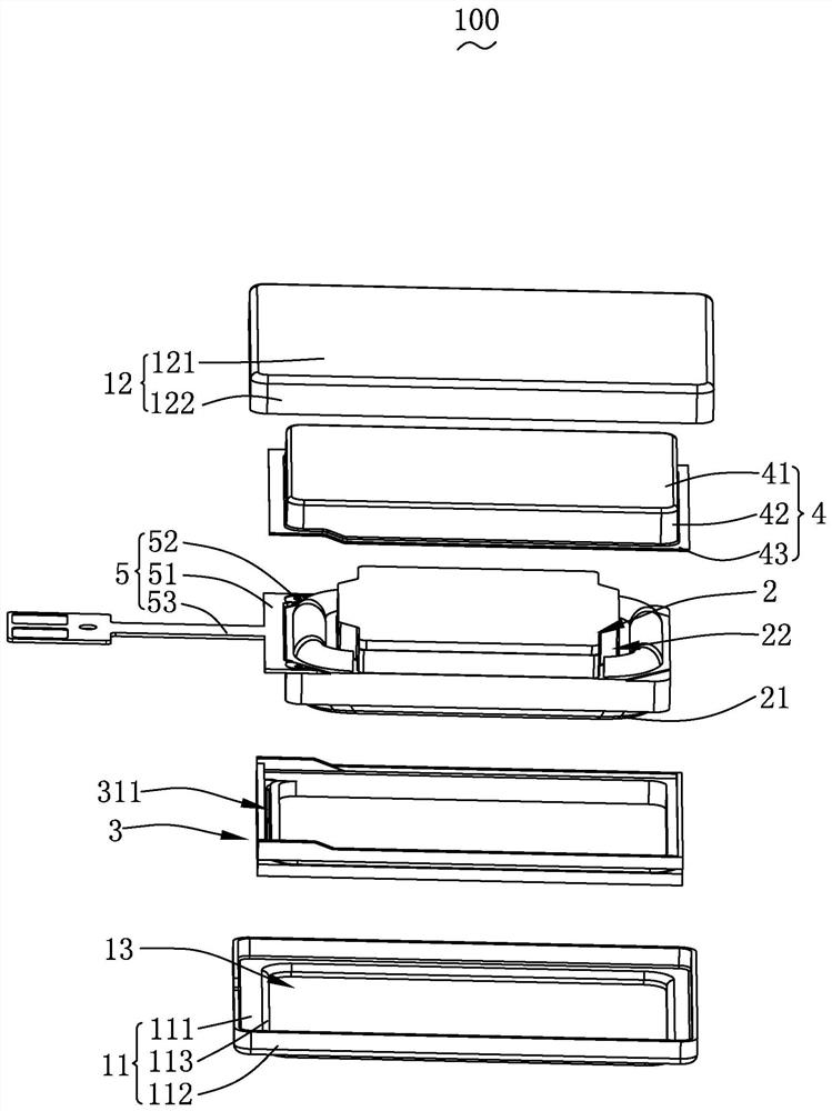
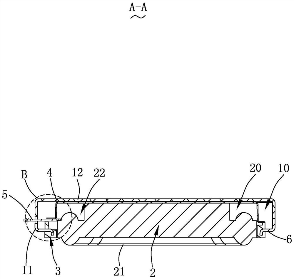
[0025] Please also see Figure 1-4 , the present invention provides a speaker box 100, which includes a housing 1, a sounding unit 2 fixedly accommodated in the housing 1 and a bracket 3 partially located in the housing 1, the sounding unit 2 Together with the housing 1, a rear acoustic cavity 20 is formed.

[0026] The housing 1 includes a front cover 11 made of metal material, a rear cover 12 made of metal material fixed on the front cover 11 , and a sound out


PUM


Abstract

The invention provides a loudspeaker box, and the loudspeaker box comprises a shell and a sound production monomer fixedly accommodated in the shell; the sound production monomer and the shell jointlyenclose a rear sound cavity, the sound production monomer comprises a vibrating diaphragm for vibration sound production, and the shell comprises a front cover, a rear cover and a sound outlet penetrating through the front cover; the front cover comprises a front cover body, a front cover outer side wall extending from the front cover body and a front cover inner side wall extending from the front cover body. The loudspeaker box further comprises a support, the side, provided with the vibrating diaphragm, of the sound production single body faces the sound outlet, the support comprises a support body and a support extension wall, the inner side wall of the front cover is completely embedded in the support body, and at least part of the front cover body is embedded in the support body; thesupport body is arranged around the periphery of the sound production single body and forms sealed fixation with the sound production single body. The sound production unit, the support, the front cover and the rear cover jointly form a closed rear sound cavity. Compared with the prior art, the loudspeaker box is large in cavity size and good in acoustic performance.

Description


Claims


Application Information

Patent Timeline
Owner RUISHENG NEW ENERGY DEV CHANGZHOU
Why Eureka
Try Eureka