Lock cylinder steel ball press riveting equipment

A technology of steel balls and lock cylinders, applied in metal processing equipment, metal processing, manufacturing tools, etc., can solve the problems of beating on artificial hands, insufficient beating of steel balls, and low assembly efficiency, so as to reduce labor force, reduce manpower, and develop low cost effect

Pending Publication Date: 2021-01-01
湖北和乐门业有限公司
View PDF0 Cites 0 Cited by
  • Summary
  • Abstract
  • Description
  • Claims
  • Application Information

AI Technical Summary

Problems solved by technology

[0002] The lock cylinder of the door lock needs to be equipped with steel balls. At present, in this process, the steel balls are manually loaded one by one, and then the steel balls are hammered to the top surface of the lock cylinder with a hammer. Some steel balls are not knocked in place, and the lock cylinder is damaged or knocked. Risks in manual hands, low assembly efficiency

Method used


Image

  • Lock cylinder steel ball press riveting equipment
  • Lock cylinder steel ball press riveting equipment
  • Lock cylinder steel ball press riveting equipment

Examples


Example Embodiment

[0028] Embodiment 1:

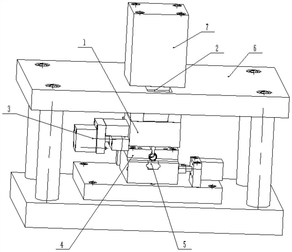
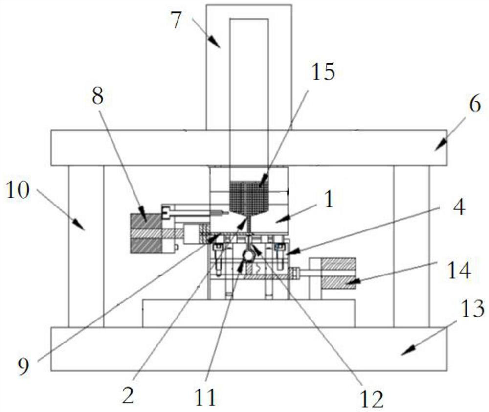
[0029] like Figure 1-7 As shown, a lock core steel ball pressure riveting equipment includes: an upper die assembly and a lower die assembly that cooperate with each other, the upper die assembly includes an upper die fixing seat 6 and an upper die head 7, the upper die head 7 is arranged on the upper side of the upper die fixing seat 6 , the upper template 1 is connected to the lower side of the upper die fixing seat 6 , and the inlet end of the hopper 2 is arranged through the upper die fixing seat 6 . When in use, the upper die head 7 is connected with the punch press to transmit the power of the punch press to the upper die assembly to complete the riveting.

[0030] The lower part of the upper die assembly is connected with an upper die plate 1 and a hopper 2, the hopper 2 is built in the upper die plate 1, and the inlet end of the hopper 2 is arranged through the upper die component, which is convenient for putting steel balls 15, and the hopper 2


PUM


Abstract

The invention discloses lock cylinder steel ball press riveting equipment, and belongs to the technical field of door matched lock cylinders. The rivet pressing equipment comprises an upper die assembly and a lower die assembly which are matched with each other, the lower portion of the upper die assembly is connected with an upper die plate and a hopper, the hopper is arranged in the upper die plate, the inlet end of the hopper penetrates through the upper die assembly, the outlet end of the hopper penetrates through the upper die plate, and the upper die plate is movably connected with a partition plate assembly used for opening or closing the outlet end of the hopper; and a positioning block assembly is arranged on the lower die assembly, a positioning groove corresponding to the outletend of the hopper is formed in the positioning block assembly, a positioning bottom plate assembly movably connected with the positioning groove is arranged in the positioning groove, a first positioning part and a second positioning part which are used for positioning the lock cylinder are arranged on the positioning bottom plate assembly, and during riveting, the positioning bottom plate assembly and the partition plate assembly are staggered. By means of the rivet pressing equipment, the yield, quality, safety and other coefficients can be improved, meanwhile, very large labor force is relieved, and safety and reliability are achieved.

Description


Claims


Application Information

Patent Timeline
Owner 湖北和乐门业有限公司
Why Eureka
Try Eureka