Mold closing device and mold closing method for three-post insulator mold

A mold clamping device and insulator technology, which is applied in the field of mold clamping device for three-pillar insulator molds, can solve problems such as residual metal foreign matter and bad insulators, and achieve the effects of preventing movement, stable support, and convenient hoisting

Pending Publication Date: 2021-01-01
HENAN PINGGAO ELECTRIC +2
View PDF4 Cites 2 Cited by
  • Summary
  • Abstract
  • Description
  • Claims
  • Application Information

AI Technical Summary

Benefits of technology

This technology allows for precise placement of a removable part called an upper die plate onto a lower baseplate by supporting it along one side and aligns its location within certain dimensions. By placing these parts together at specific locations, there will be fewer problems associated with any damage caused due to external factors like impact force. Additionally, if the removal tool needs to lift up the entire assembly before reclining them again, they won't hit other components causing damages. Overall, this design improving stability and reducing wear between different materials helps improve productivity efficiency.

Problems solved by technology

This patented technical problem addressed by this patents relating to the design of high pressure gas insulators used within transmission lines (Gilts) involves ensuring that there is no gap between different parts when closed together without any alignment issues during manufacture. Additionally, the use of an intermediate layer called a foam reduces unwanted materials from entering the space inside the insulation system due to its low dielectric constant compared to traditional methods like air filling.

Method used


Image

  • Mold closing device and mold closing method for three-post insulator mold
  • Mold closing device and mold closing method for three-post insulator mold

Examples


specific Embodiment 1

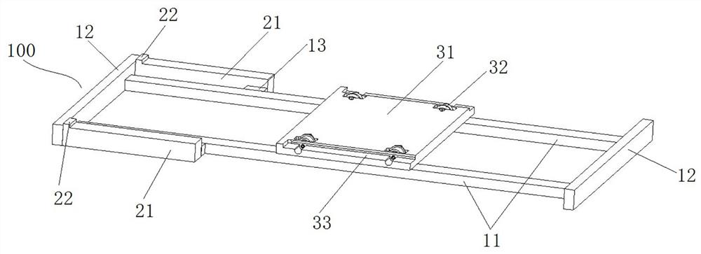
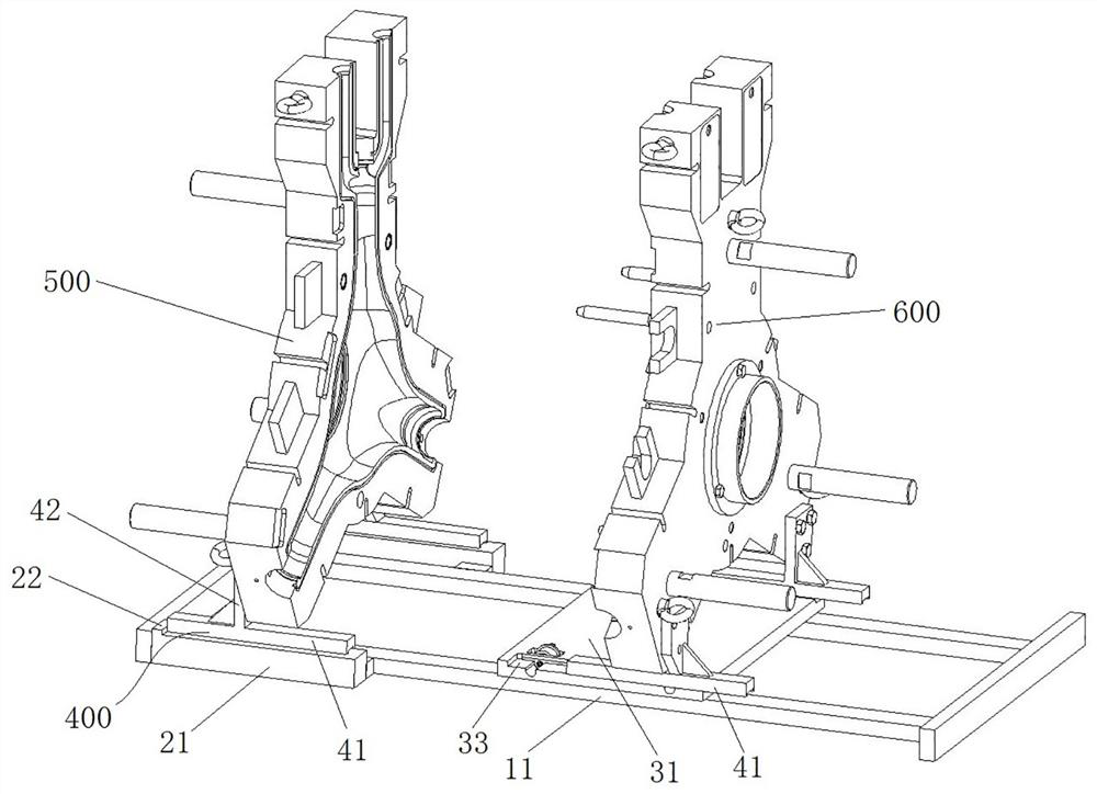
[0040] Such as figure 1 and figure 2 As shown, the clamping device includes a support frame 100, on which the positioning end half-mold support table 21 is fixedly installed, and the movable end half-mold support table 31 is equipped with a movable end half-mold support table 31 for guiding and moving along the left and right directions, and the movable end half-mold support table 31 The movement realizes the splitting and closing of the half-mold 500 at the positioning end and the half-mold 600 at the movable end.

[0041] The support frame 100 includes two guide rails 11 extending in parallel. The guide rails 11 extend left and right. The support frame 100 also includes an end connection 12 connecting the left end and the right end of the two guide rails 11. The end connection 12 is a column or a plate to strengthen the support. The overall strength of the frame 100.

[0042] Such as figure 1 As shown, there are two half-mold support platforms 21 at the positioning end, and

Embodiment 1

[0058] In Embodiment 1, the support frame includes two guide rails extending in parallel, and the half-mold support platform at the movable end realizes guiding cooperation with the guide rails through track wheels. In this embodiment, a dovetail groove extending in the left and right direction is provided at the bottom of the mold half support platform at the movable end, and the guide rail is used in conjunction with the dovetail groove to guide the mold support platform half at the movable end. Or, the supporting frame can be a plate body, a dovetail groove is provided on the plate body, and guide rails are fixedly installed at the bottom of the half-mould supporting platform at the movable end.

specific Embodiment 3

[0060] In Embodiment 1, the mold clamping device includes legs, and the legs are fixedly installed on the mold half when in use. In this embodiment, when the lower end of the half-mold has a certain width and can be placed stably, the supporting legs can be canceled and the half-mold can be directly placed on the support platform. After the support leg is cancelled, the stop boss and the positioning part directly cooperate with the half mold. It should be noted that regardless of whether there are legs or not, it is necessary to ensure that the two mold halves are kept at the same level to achieve a centered arrangement.


PUM


Abstract

The invention relates to a mold closing device and mold closing method for a three-post insulator mold. The mold closing device comprises a support frame, the support frame is provided with two positioning end half-mold support tables, the two positioning end half-mold support tables are arranged at an interval, the interval arrangement direction of the two positioning end half-mold support tablesis defined as the front-back direction, during use, a positioning half mold is placed on the positioning end half-mold support tables, and a central cylinder mounting hole extends left and right; a movable end half-mold support table is assembled on the support frame in a guiding mode in the left-right direction, when the movable end half-mold support table is used, a movable end half mold is placed on the movable end half-mold support table, and a center cylinder mounting hole extends left and right; and a channel extending left and right is formed between the two positioning end half-mold support tables, and the width, in the front-back direction, of the movable end half-mold support table is smaller than or equal to the width of the channel, so that the movable end half-mold support table can be inserted into the channel for mold closing.

Description


Claims


Application Information

Patent Timeline
Owner HENAN PINGGAO ELECTRIC
Why Eureka
Try Eureka