All-attitude calculation method for holder

A calculation method, full-attitude technology, used in measurement devices, instruments, surveying and navigation, etc.

Inactive Publication Date: 2021-01-15
郑州天一飞控机电有限公司
View PDF9 Cites 3 Cited by
  • Summary
  • Abstract
  • Description
  • Claims
  • Application Information

AI Technical Summary

Problems solved by technology

[0004] The present invention aims at the problem that existing pan-tilt attitude tracking methods cannot autonomously calculate the pitch angle, ro

Method used


Image

  • All-attitude calculation method for holder
  • All-attitude calculation method for holder
  • All-attitude calculation method for holder

Examples


Embodiment Construction

[0030] The present invention will be further explained below in conjunction with accompanying drawing and specific embodiment:

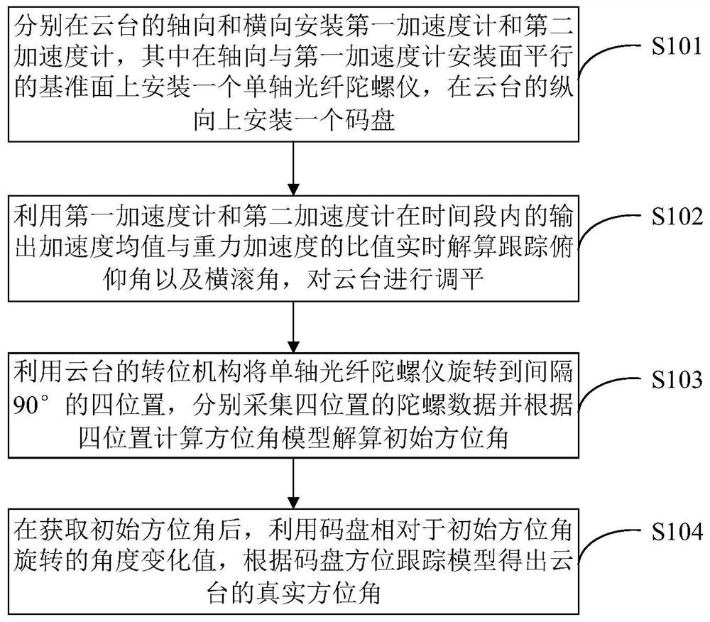
[0031] Such as figure 1 As shown, a method for calculating the full attitude of the pan / tilt is suitable for the ground pan / tilt device that needs to display the pitch angle, roll angle and azimuth in real time, including:

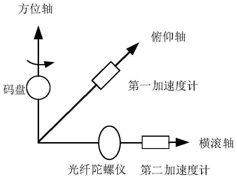
[0032] Step S101: install a first accelerometer and a second accelerometer on the axial (pitch axis) and lateral (roll axis) of the gimbal respectively, wherein one is installed on the reference plane parallel to the first accelerometer mounting surface in the axial direction For a single-axis fiber optic gyroscope, a code disc is installed in the longitudinal direction of the pan / tilt. The schematic diagram of the device installation is as follows: figure 2 Shown; Specifically, the cloud platform has a multi-position indexing mechanism.

[0033] Step S102: When the rate of change of the pitch axis and roll axis of the gimb


PUM


Abstract

The invention discloses an all-attitude calculation method for a holder, and the method comprises the following steps: respectively mounting a first accelerometer and a second accelerometer in the axial direction and the transverse direction of the holder, mounting a single-axis optical fiber gyroscope on a reference plane parallel to the mounting surface of the first accelerometer in the axial direction, and mounting a coded disc in the longitudinal direction of the holder; calculating a tracking pitch angle and a roll angle in real time by using a ratio of an output acceleration mean value to a gravitational acceleration of the first accelerometer and the second accelerometer in a time period, and leveling the holder; rotating the single-axis optical fiber gyroscope to four positions atan interval of 90 degrees by using an indexing mechanism of a cradle head, respectively acquiring gyroscope data of the four positions, and calculating an initial azimuth angle according to an azimuthangle model calculated by the four positions; after the initial azimuth angle is obtained, obtaining the real azimuth angle of the holder according to the coded disc azimuth tracking model by utilizing the angle change value of the coded disc relative to the initial azimuth angle. According to the invention, the pitch angle, roll angle and azimuth angle of the holder can be calculated autonomously in real time.

Description


Claims


Application Information

Patent Timeline
Owner 郑州天一飞控机电有限公司
Why Eureka
Try Eureka