Dual-mode switch box

A switch box, dual-mode technology, applied in the aerospace field, can solve problems such as affecting the reliability of life-saving products, greatly affecting the electronic components, reducing the overall life of the product, etc., to improve the anti-electromagnetic environment interference ability, and the internal structure is compact. , the effect of simple wiring

Pending Publication Date: 2021-01-26
沈阳兴华航空电器有限责任公司
View PDF0 Cites 0 Cited by
  • Summary
  • Abstract
  • Description
  • Claims
  • Application Information

AI Technical Summary

Benefits of technology

This technology provides an improved design for electric guiding devices used during maintenance work without adding extra parts or requiring complicated assembly processes. It includes springs at one end of the device's fixed mounting board, matching different types of bolts on other ends. These features help prevent accidental movement caused by external factors like vibrations from affecting the operation of these devices. Additionally, there are various technical improvements such as reducing size and improving efficiency while maintaining their overall functioniveness over time. Overall, this innovation makes them more reliable and efficient than existing designs.

Problems solved by technology

This patented technical problem addressed in this patents relates to improving the durability and lifetimes of aircraft equipment used for flight operations during extreme environments such as impact from strong external forces like lightning strikes or explosions caused by firearms.

Method used


Image

  • Dual-mode switch box
  • Dual-mode switch box
  • Dual-mode switch box

Examples


Embodiment Construction

[0019] The present invention will be described in detail below with reference to the accompanying drawings.

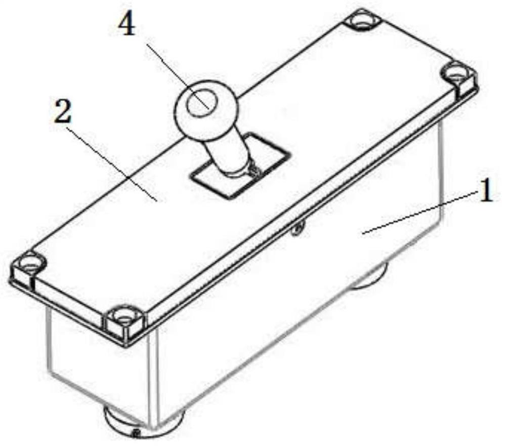
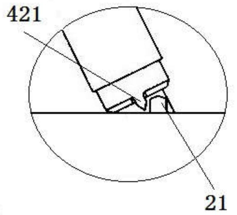
[0020] like Figure 1-Figure 5 As shown, a dual-mode switch box includes a housing 1, a mounting panel 2, a mounting bottom plate 3, a crank link mechanism 4, a switch box assembly 5, a first electrical connector 6, a second electrical connector 7 and wires, A first electrical connector 6, a switch box assembly 5 and a second electrical connector 7 are fixed on the mounting base plate 3 in sequence from left to right, and the casing 1 is vertically fixed on the top surface of the mounting base 3, so The housing 1 has a cavity inside, the bottom edge of the housing 1 is flush with the edge of the top surface of the mounting base plate 3, the mounting panel 2 is vertically fixed on the top of the housing 1, and the center of the mounting panel 2 has a crank arm. The opening of the connecting rod mechanism 4, the middle section of the crank connecting rod mechanism 4 is rot


PUM


Abstract

The invention relates to the technical field of aerospace, in particular to a dual-mode switch box, which comprises a shell, a mounting panel, a mounting bottom plate, a crank connecting rod mechanism, a switch box assembly, a first electric connector, a second electric connector and a wire, and is characterized in that the first electric connector, the switch box assembly and the second electricconnector are sequentially fixed on the mounting bottom plate from left to right; the shell is vertically fixed to the top face of the mounting bottom plate, a cavity is formed in the shell, the edgeof the bottom of the shell is flush with the edge of the top face of the mounting bottom plate, the mounting panel is vertically fixed to the top of the shell, and an opening allowing the crank-link mechanism to move is formed in the center of the mounting panel. The middle section of the crank connecting rod mechanism is rotatably connected into the opening through a rivet, the tail end of the crank connecting rod mechanism is connected with the switch box assembly, the crank connecting rod mechanism is provided with a first protruding block, the mounting panel is provided with a second protruding block for limiting the position of the first protruding block, and the switch box assembly has the advantages of being small in size, capable of preventing misoperation and the like.

Description


Claims


Application Information

Patent Timeline
Owner 沈阳兴华航空电器有限责任公司
Why Eureka
Try Eureka