Shell rotary-type clamping needle fixing dental implant structure and use method

A rotary, dental implant technology, applied in dental implants, dentistry, orthodontics, etc., can solve secondary injuries, inconvenient use, etc., and achieve the effects of easy operation, convenient installation, and convenient driving

Active Publication Date: 2021-03-05
ZHUHAI PEOPLES HOSPITAL GUANGDONG PROVINCE
View PDF7 Cites 0 Cited by
  • Summary
  • Abstract
  • Description
  • Claims
  • Application Information

AI Technical Summary

Benefits of technology

This patented technology provides technical benefits that make teeth surgery easier and safer. It involves attaching a device called a dentist's drill bit (or other tool) inside or attached on top of a patient's jawbone through use of a special mechanism known as a socket system. By driving this attachment process, there will be no damaging impact upon any part around them during installation. Additionally, these devices allow for quick removal after they were installed due to their own locking properties. Overall, this design makes procedures faster and less invasive compared to traditional methods like welding metal rods used for orthodontic treatment.

Problems solved by technology

This patented technical problem addressed by this patents relates how to secure an artificial dental prosthetic device (such as a crown) that can be fixed effectively without causing damage or discomfort for patients who require it due to its placement inside their mouths during orthodontic treatment.

Method used


Image

  • Shell rotary-type clamping needle fixing dental implant structure and use method
  • Shell rotary-type clamping needle fixing dental implant structure and use method
  • Shell rotary-type clamping needle fixing dental implant structure and use method

Examples


Embodiment Construction

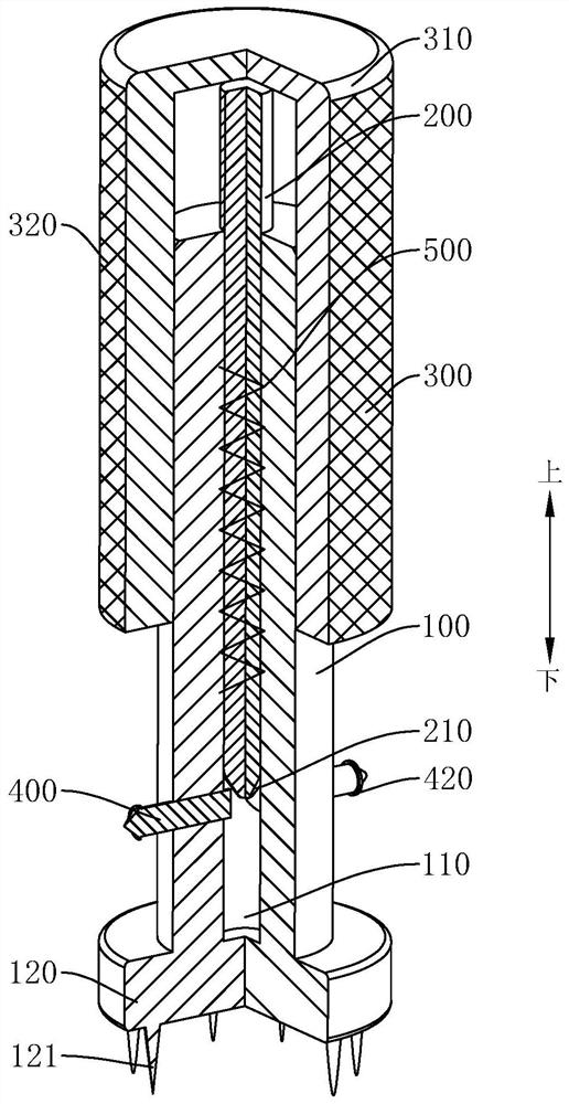
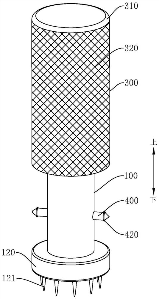
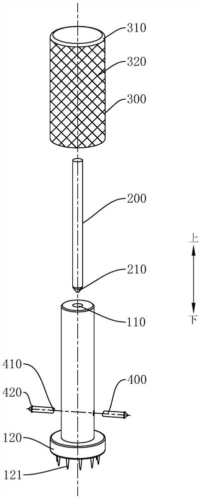
[0029] Embodiments of the present invention are described in detail below, and examples of the embodiments are shown in the drawings, wherein the same or similar reference numerals denote the same or similar elements or elements having the same or similar functions throughout. The embodiments described below by referring to the figures are exemplary only for explaining the present invention and should not be construed as limiting the present invention.

[0030] In the description of the present invention, it should be understood that the orientation descriptions, such as up, down, front, back, left, right, etc. indicated orientations or positional relationships are based on the orientations or positional relationships shown in the drawings, and are only In order to facilitate the description of the present invention and simplify the description, it does not indicate or imply that the device or element referred to must have a specific orientation, be constructed and operated in a s


PUM


Abstract

The invention discloses a shell rotary-type clamping needle fixing dental implant structure and a use method, the shell rotary-type clamping needle fixing dental implant structure is used for alveolarbone, and the shell rotary-type clamping needle fixing dental implant structure comprises an implanting rod with an inserting hole formed along the axial direction; a inserting rod to be inserted into the inserting hole; a shell to be connected to the implanting rod in a sleeved mode and in threaded connection with the implanting rod; two clamping needles to be connected to the implanting rod through a second elastic piece, the two clamping needles are oppositely arranged, notches are formed in the opposite ends of the two clamping needles, and the second elastic piece is used for driving theclamping needles to move in the axis direction of the implanting rod; and the shell is used for driving the inserting rod to be inserted into the notches to drive the clamping needles to protrude from the peripheral wall of the shell. The shell is arranged for driving the clamping needles to be inserted into the alveolar bone, so that the dental implant structure is convenient to operate and use;due to the fact that the shell and the clamping needles are arranged, so that damage to the alveolar bone caused by screw-in of threads can be avoided when the dental implant structure is implanted;and the diameter of the arranged shell is larger than that of the implanting rod, thus being more convenient when driving.

Description


Claims


Application Information

Patent Timeline
Owner ZHUHAI PEOPLES HOSPITAL GUANGDONG PROVINCE
Why Eureka
Try Eureka