Automatic screwdriver

A screwdriver and automatic technology, applied to screwdrivers, motor tools, wrench, etc., can solve the problems of low processing efficiency, high production cost, low work efficiency, etc., and achieve the effect of improving work efficiency

Inactive Publication Date: 2021-03-09
江门市江海区柏健电器制造有限公司
View PDF0 Cites 0 Cited by
  • Summary
  • Abstract
  • Description
  • Claims
  • Application Information

AI Technical Summary

Benefits of technology

This patented design allows for easy loading or unloading screwdrivers by providing an adapter that connects to a flexible supply line used during operation. When it's time to use one tool, another tool becomes available without having them being taken up on their own hands while they are still working. Additionally, there may also have a mechanism where the scanner itself moves backward after each step until its desired location has been reached. Overall, these technical improvements make the process more efficient than manual tools like those described earlier.

Problems solved by technology

The technical problem addressed in this patented text relates to manual screw removing during maintenance procedures for machinery that require frequent replacement with different types of screw heads such as threaded bolts and nuts. This can be challenging because it requires multiple steps involving human effort and slow down overall process times while also increasing costs associated therewith due to increased manpower required by operators who have limited hands abilities.

Method used


Image

  • Automatic screwdriver
  • Automatic screwdriver
  • Automatic screwdriver

Examples


Embodiment Construction

[0025] Embodiments of the present invention are described in detail below, examples of which are shown in the drawings, wherein the same or similar reference numerals designate the same or similar elements or elements having the same or similar functions throughout. The embodiments described below by referring to the figures are exemplary only for explaining the present invention and should not be construed as limiting the present invention.

[0026] In describing the present invention, it should be understood that the terms "center", "longitudinal", "transverse", "length", "width", "thickness", "upper", "lower", "front", " Rear", "Left", "Right", "Vertical", "Horizontal", "Top", "Bottom", "Inner", "Outer", "Axial", "Radial", "Circumferential" The orientation or positional relationship indicated by etc. is based on the orientation or positional relationship shown in the drawings, and is only for the convenience of describing the present invention and simplifying the description,


PUM


Abstract

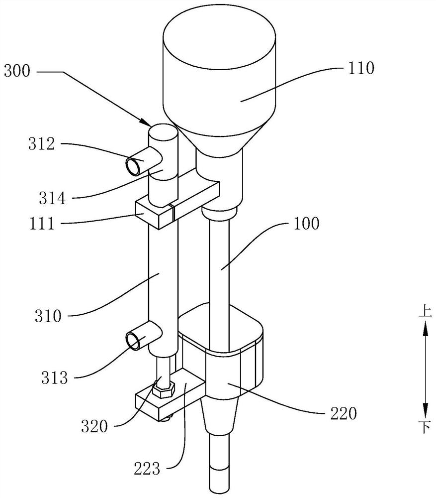
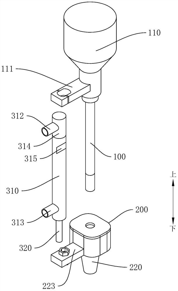
The invention discloses an automatic screwdriver. The automatic screwdriver comprises a screwdriver body, a conveying mechanism and a lifting device, wherein the conveying mechanism comprises a hose and a feeding end, a vertically-through central conical hole is formed in the feeding end, and the central conical hole is formed in the screwdriver body in a sleeving mode and can slide relative to the screwdriver body; the hose is connected with the feeding end and used for supplying screws to the feeding end; the lifting device comprises a fixed cylinder and a lifting connecting rod, one end ofthe lifting connecting rod is arranged in the fixed cylinder in a penetrating mode, and the other end of the lifting connecting rod is connected with the feeding end; and the fixed cylinder is connected with a device capable of driving the lifting connecting rod to ascend and descend, and the lifting connecting rod can drive the feeding end to ascend and descend during ascending and descending. According to the automatic screwdriver provided by the embodiment of the invention, a screw does not need to be manually held by a worker, convenience and quickness are achieved, and the working efficiency is improved.

Description


Claims


Application Information

Patent Timeline
Owner 江门市江海区柏健电器制造有限公司
Why Eureka
Try Eureka