Machine vision calibration method for Stewart platform kinematics parameters

A technology of kinematic parameters and calibration methods, applied in the fields of machine vision and robotics, can solve problems such as increasing calibration costs

Pending Publication Date: 2021-05-07
ZHEJIANG UNIV
View PDF0 Cites 3 Cited by
  • Summary
  • Abstract
  • Description
  • Claims
  • Application Information

AI Technical Summary

Problems solved by technology

[0009] The above traditional methods need to accurately measure the absolute poses of the lower platform and the upper platform during cali

Method used


Image

  • Machine vision calibration method for Stewart platform kinematics parameters
  • Machine vision calibration method for Stewart platform kinematics parameters
  • Machine vision calibration method for Stewart platform kinematics parameters

Examples


Embodiment Construction

[0038] The present invention will be described in further detail below in conjunction with the accompanying drawings and specific embodiments, and the purpose and effects of the present invention will become more apparent.

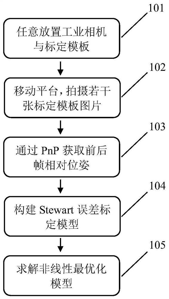
[0039] The invention proposes an online calibration method for kinematic parameters of a Stewart platform based on machine vision. figure 1 The flow chart of the method created by the present invention is given, and the method proposed by the present invention can well use only relative pose information, and when the prior information such as the transformation relationship between the camera coordinate system and the upper platform coordinate system is unknown, At the same time, the calibration of the kinematic parameters of the Stewart platform and the estimation of the transformation matrix of the camera coordinate system and the platform coordinate system are completed.

[0040] The Stewart platform is a parallel structure platform with six degrees of fre


PUM


Abstract

The invention discloses a machine vision calibration method for kinematics parameters of a Stewart platform, and the method comprises the steps: placing a camera on an upper platform of the Stewart platform, then moving the upper platform to a specific pose for a plurality of times, shooting an image of a calibration template after each movement, detecting pixel coordinates of cross points on a checkerboard calibration template in an image through an angular point detection method, solving a Perspective-n-Point problem to obtain the pose of a camera relative to the calibration template, finally, constructing an equality constraint kinematics parameter error model, and converting the model into an unconstrained model to carry out optimization solution. According to the kinematics parameter calibration method provided by the invention, the kinematics parameters can be obtained only through the relative pose change under the condition that the transformation relation between the camera coordinate system and the upper platform coordinate system is unknown, and the error of the initial length of the supporting rod can be effectively determined.

Description


Claims


Application Information

Patent Timeline
Owner ZHEJIANG UNIV
Why Eureka
Try Eureka