Locking assembly and ground anchor with same

A component and locking technology, applied in the direction of pipes/pipe joints/fittings, pipe supports, mechanical equipment, etc., can solve the problem of time-consuming and labor-intensive fixing of pipelines, and achieve the effect of saving installation time, simple structure and improving efficiency.

Pending Publication Date: 2021-05-11
天津市合力机械制造有限公司
View PDF0 Cites 0 Cited by
  • Summary
  • Abstract
  • Description
  • Claims
  • Application Information

AI Technical Summary

Benefits of technology

This patented device has two main technical features: one for connecting an anchoring system with another part (the compressor), while avoids having to turn around it during fitting or attaching them together. Another aspect involves making sure that all parts have been properly aligned before joining them, which improves their overall performance over existing systems.

Problems solved by technology

This patented problem addressed by this patents relates to fixing buried pipes during underground operations such as wellbores drilled through earth formations for various purposes like transportation infrastructure development. These pipes can be made up from different materials including steel tubular members (such as welded seamless iron), reinforced concrete bars/plants, cables, etc., but they may have many types of joint connections due to their complexity. Prior methods require complex assembly steps involving numerous tools and long periods of workmanship.

Method used


Image

  • Locking assembly and ground anchor with same
  • Locking assembly and ground anchor with same
  • Locking assembly and ground anchor with same

Examples


Embodiment 1

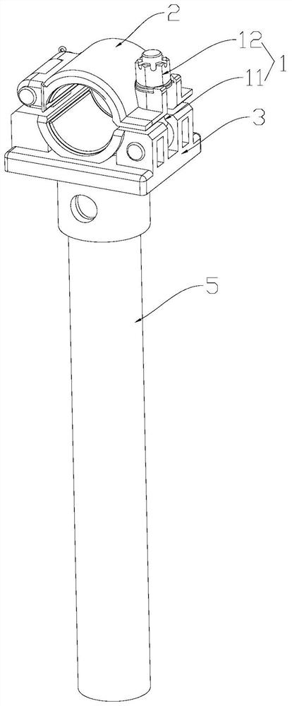
[0033] Such as Figure 1-Figure 7 , this embodiment provides a locking assembly 1, including a rotating body 11 and a locking member 12 located on the rotating body 11, wherein: the rotating body 11 is connected to any one of the ground anchor body 3 and the gland 2 and the other of the two is provided with a receiving part; the rotating body 11 can be rotated into the receiving part, and the position of the locking part 12 on the rotating body 11 can be adjusted until the locking part 12 abuts against the receiving part to push the pressure The cover 2 is fastened to the ground anchor body 3; at the same time, the pipeline between the gland 2 and the ground anchor body 3 can be fixed.

[0034] Further, the rotating body 11 can extend into the receiving part from the side of the receiving part by turning, and the locking part 12 located above the receiving part can adjust the position on the rotating body 11 until the locking part 12 abuts against the receiving part .

[0035]

Embodiment 2

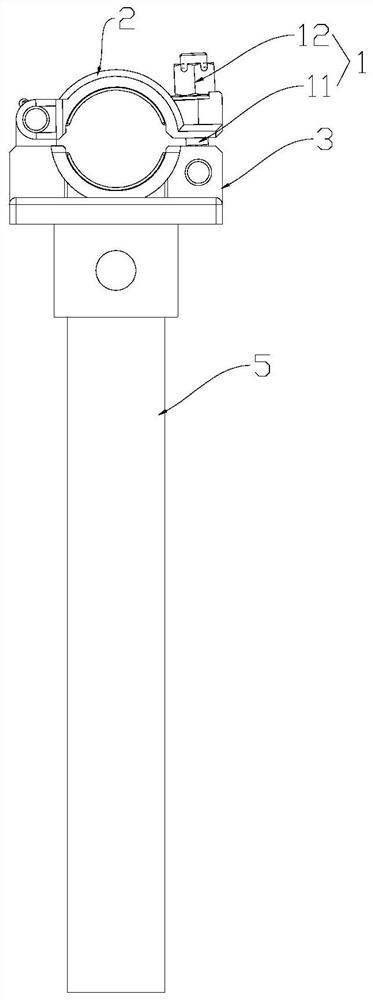
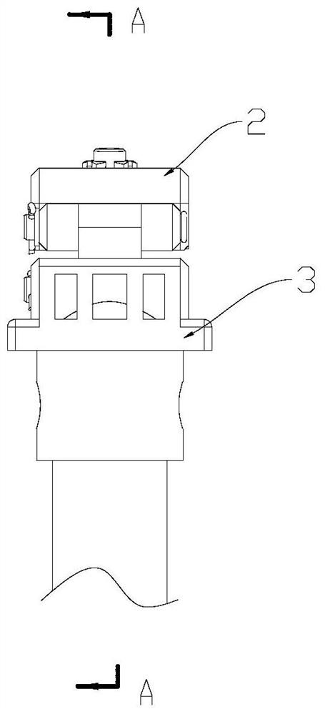
[0055] This embodiment provides a ground anchor, see Figure 1-Figure 4 As shown, the above-mentioned ground anchor includes a ground anchor body 3, a gland 2 and the above-mentioned locking assembly 1. The first side of the ground anchor body 3 and the gland 2 is fastened by the locking assembly 1, and the second side of the two is hinged.

[0056] In the ground anchor in this embodiment, the first side of the ground anchor body 3 and the gland 2 are fastened by the locking assembly 1, and the second side of the two is hinged; the ground anchor body 3 and the gland 2 are hinged together, and the fixed After the pipeline is finished, it is only necessary to rotate the rotating body 11 on one side and tighten a locking piece 12 to complete the assembly of the gland 2 and the ground anchor body 3. Compared with the prior art and the ground anchor body 3 and the gland 2 In terms of the structure in which the above-mentioned locking assembly 1 is used to fix both sides of the structu


PUM


Abstract

The invention provides a locking assembly and a ground anchor with the same, relates to the technical field of oil field construction, and solves the technical problem that a connecting structure of a ground anchor body and a gland wastes time and labor to fix a pipeline. The locking assembly comprises a rotating body and a locking piece located on the rotating body, wherein the rotating body is connected to any one of the ground anchor body and the gland, the other one of the ground anchor body and the gland is provided with a containing part, the rotating body can rotate into the containing part, and the position of the locking piece on the rotating body is adjusted till the locking piece abuts against the containing part so that the gland and the ground anchor body can be fastened. The locking assembly is used for fixing ground pipelines, according to the ground anchor with the locking assembly, a plurality of bolt and nut assemblies do not need to be sequentially screwed in and tightly screwed on the gland and the ground anchor body, fastening of the ground anchor body and the gland can be completed only by rotating the rotating body and adjusting the position of the locking piece, the connecting structure is simple, time and labor are saved in installation, the pipeline fixing efficiency is improved, labor is reduced, and construction time is saved.

Description


Claims


Application Information

Patent Timeline
Owner 天津市合力机械制造有限公司
Why Eureka
Try Eureka