Positioning detection method and positioning detection device
A positioning detection device and positioning detection technology, applied in the field of visual detection, can solve the problems of product yield reduction, error prone detection results, lack of automatic detection, etc., and achieve the effect of improving detection accuracy and product yield
- Summary
- Abstract
- Description
- Claims
- Application Information
AI Technical Summary
Benefits of technology
Problems solved by technology
Method used
Image


Examples
Embodiment 1
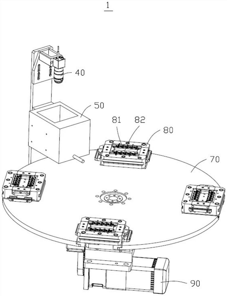
[0077] see figure 1 , 2 As shown, it is a schematic structural diagram and a schematic block diagram of a positioning detection device provided by an embodiment of the present application. The positioning detection device 1 is used to detect whether the positioning of the first workpiece 81 and the second workpiece 82 is qualified.
[0078] The position detection device 1 includes, but not limited to, a processor 10 , a memory 20 , an image picker 40 , a light source 50 , a display screen 60 and a computer program 30 stored in the memory 20 and operable on the processor 10 . The memory 20 , image picker 40 , light source 50 and display screen 60 are respectively coupled to the processor 10 . The computer program 30 of this embodiment is a positioning detection program. The location detection method is realized when the processor 10 executes the computer program 30 .
[0079] In one embodiment, the image picker 40 is used to collect a first image, which includes images of at l
Embodiment 2
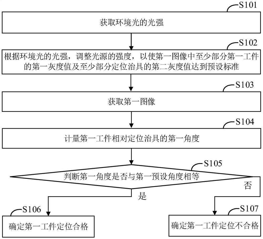
[0098] see image 3 As shown in FIG. 1 , it is a flowchart of a location detection method according to an embodiment of the present application. According to different requirements, the order of the steps in the flowchart can be changed, and some steps can be omitted.
[0099] In one embodiment, the positioning detection method is used to detect whether the positioning of the first workpiece on the positioning jig is qualified.
[0100] Step S101, acquiring the light intensity of ambient light.
[0101] In one embodiment, the illumination intensity of the ambient light of the positioning detection device 1 is acquired by a light sensor, and then the value of the illumination intensity is transmitted to the processor. The light sensor can be an independent sensing device, or a component integrated in the image picker. That is, in this step, the light intensity can also be acquired by the image sensor, and then the value of the light intensity can be sent to the processor.
[0
Embodiment 3
[0125] see Figure 4 As shown in FIG. 2 , it is a flow chart of a positioning detection method according to another embodiment of the present application. According to different requirements, the order of the steps in the flowchart can be changed, and some steps can be omitted.
[0126] Step S201, acquiring the light intensity of ambient light.
[0127] In one embodiment, the illumination intensity of the ambient light of the positioning detection device 1 is acquired by a light sensor, and then the value of the illumination intensity is transmitted to the processor. The light sensor can be an independent sensing device, or a component integrated in the image picker. That is, in another implementation manner, in this step, the image sensor may also obtain the light intensity, and then transmit the value of the light intensity to the processor.
[0128] Step S202, adjusting the intensity of the light source according to the light intensity of the ambient light, so that the firs
PUM
 Abstract
Description
Claims
Application Information
 - R&D Engineer
- R&D Manager
- IP Professional
- Industry Leading Data Capabilities
- Powerful AI technology
- Patent DNA Extraction
Browse by: Latest US Patents, China's latest patents, Technical Efficacy Thesaurus, Application Domain, Technology Topic.
© 2024 PatSnap. All rights reserved.Legal|Privacy policy|Modern Slavery Act Transparency Statement|Sitemap