Hybrid three-level bidirectional DC-DC converter and neutral-point voltage balance control method thereof
A DC-DC, three-level technology, applied in the direction of adjusting electrical variables, control/regulation systems, DC power input conversion to DC power output, etc., can solve the problem of high system cost, low efficiency, and high withstand voltage requirements of switching tubes. problem, to achieve the effect of simple control, flexible adjustment, and avoiding the increase of capacitance loss
- Summary
- Abstract
- Description
- Claims
- Application Information
AI Technical Summary
Problems solved by technology
Method used
Image

Examples
Example Embodiment
[0052]Example 1
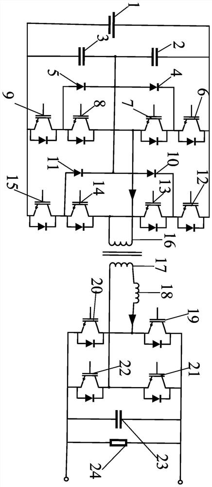
[0053]A mixed three-level DC / DC converter in the embodiment of the present invention, seefigure 1 As shown, including: DC power supply 1, voltage pressure capacitor circuit, triple circuit, transformer, H-bridge circuit, and load resistance 24;
[0054]The voltage dividing capacitor circuit includes a first capacitor 2 and a second capacitor 3 in series; both ends of the voltage supply capacitor circuit connecting the positive and negative ends of the DC power source 1;
[0055]The three-level circuit includes: a first diode 4, a second diode 5, a third diode 10, a fourth diode 11, a first switching tube 6, a second switching tube 7, a third Switching pipe 8, fourth switch tube 9, fifth switch pipe 12, sixth switch tube 13, seventh switch pipe 14 and eighth switch tube 15.
[0056]The first switching tube 6, the second switch pipe 7, the third switch pipe 8, the fourth switch pipe 9, the first diode 4 and the second diode 5 form the first half bridge arm, fifth switch tube 12
Example Embodiment
[0087]Example 2
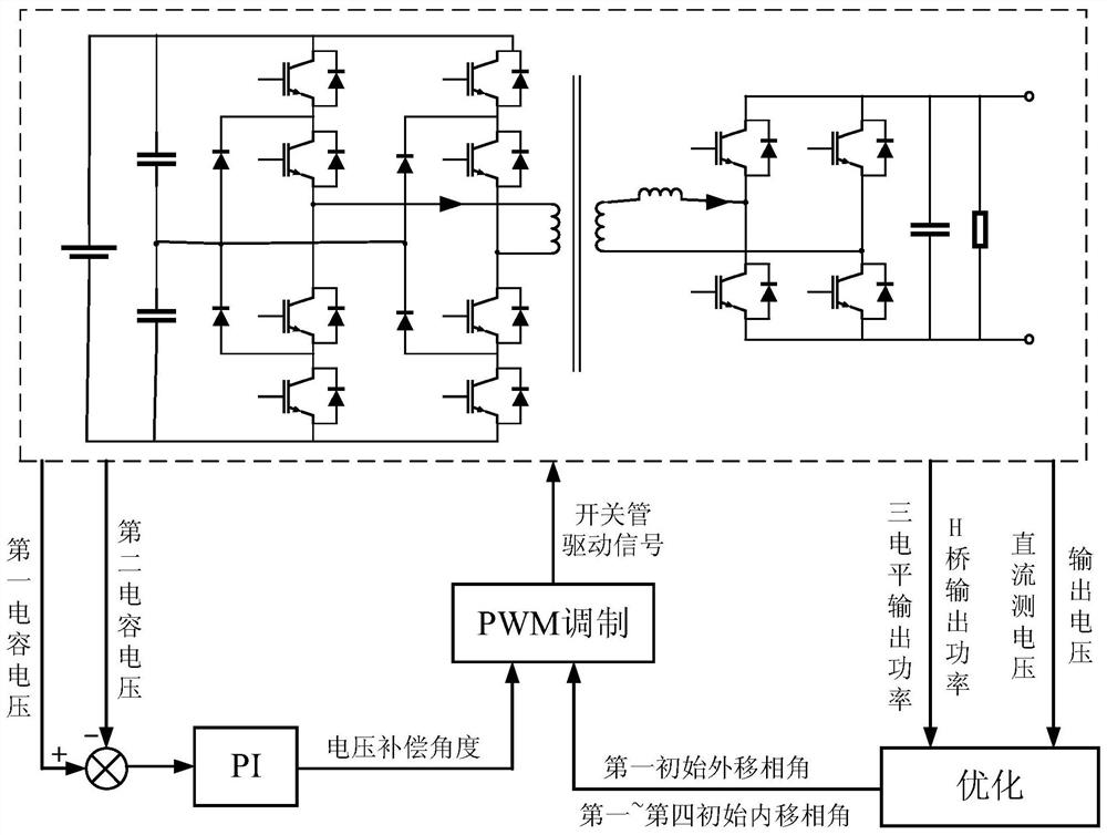
[0088]Correspondingly, the midpoint voltage balancing control method of the mixed triple-direction DC / DC converter is mixed, seeimage 3 As shown, the following procedure:
[0089]Step 1, first collect the output power, H-bridge circuit output power, DC power supply voltage, load resistance voltage of the H-bridge circuit, the output power, DC power supply voltage, and load resistance voltage of the hybrid three-directional DC / DC converter.
[0090]Step 2, according to the three-level circuit output power, the H-bridge circuit output power, the DC power supply voltage, and the load resistance voltage is optimized, the first initial linear phase angle, the second initial internal phase angle, the third initial internal phase Corner, fourth initial internal phase angle and first initial phase phase angle; wherein the first initial linen phase angle, the second initial internal phase angle, the third initial internal phase angle, the fourth initial internal movement And th
Example Embodiment
[0098]Example 3
[0099]The midpoint voltage balancing control device of a mixed triple-direction DC / DC converter of the present invention is based on the same inventive inventive in Example 2, including:
[0100]Data acquisition module, used to collect three-level circuit output power, H-bridge circuit output power, DC supply voltage, and load resistance voltage at the time of steady state operation of the transducer;
[0101]The initial shift angle calculation module is used to calculate the first internal shift angle when the converter is steady-state operation based on the three-level circuit output power, the H-bridge circuit output power, the DC supply voltage, and the load voltage. Phase angle, third internal shift angle, fourth internal shift angle, and first outer transition angle, as the first initial linen phase angle, second initial internal phase angle, third initial internal phase angle, first Fourth initial internal movement phase angle and the first initial outer shift angle
PUM
 Abstract
Description
Claims
Application Information
 - R&D Engineer
- R&D Manager
- IP Professional
- Industry Leading Data Capabilities
- Powerful AI technology
- Patent DNA Extraction
Browse by: Latest US Patents, China's latest patents, Technical Efficacy Thesaurus, Application Domain, Technology Topic.
© 2024 PatSnap. All rights reserved.Legal|Privacy policy|Modern Slavery Act Transparency Statement|Sitemap