Continuous dry-method ball mill with ultrahigh filling rate

A technology of dry ball milling and filling rate, which is applied in grain processing, etc., can solve problems such as insufficient filling rate, unsatisfactory quality and efficiency of ball milling operations, and achieve the effect of improving filling rate

Active Publication Date: 2021-06-01
淄博锦岳机械制造有限公司
View PDF8 Cites 0 Cited by
  • Summary
  • Abstract
  • Description
  • Claims
  • Application Information

AI Technical Summary

Problems solved by technology

[0003] Although there are many ball mills currently on the market, there are obvious defects in the adaptive adjustment of ball mills, continuous

Method used


Image

  • Continuous dry-method ball mill with ultrahigh filling rate
  • Continuous dry-method ball mill with ultrahigh filling rate
  • Continuous dry-method ball mill with ultrahigh filling rate

Examples


Example Embodiment

[0020]Example one

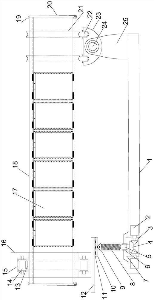
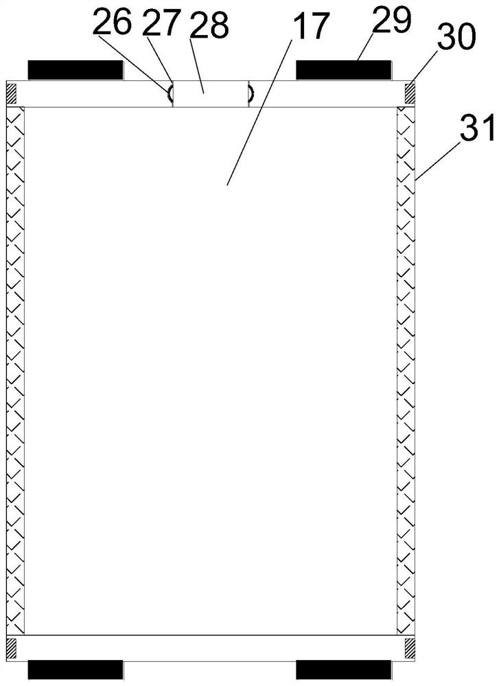
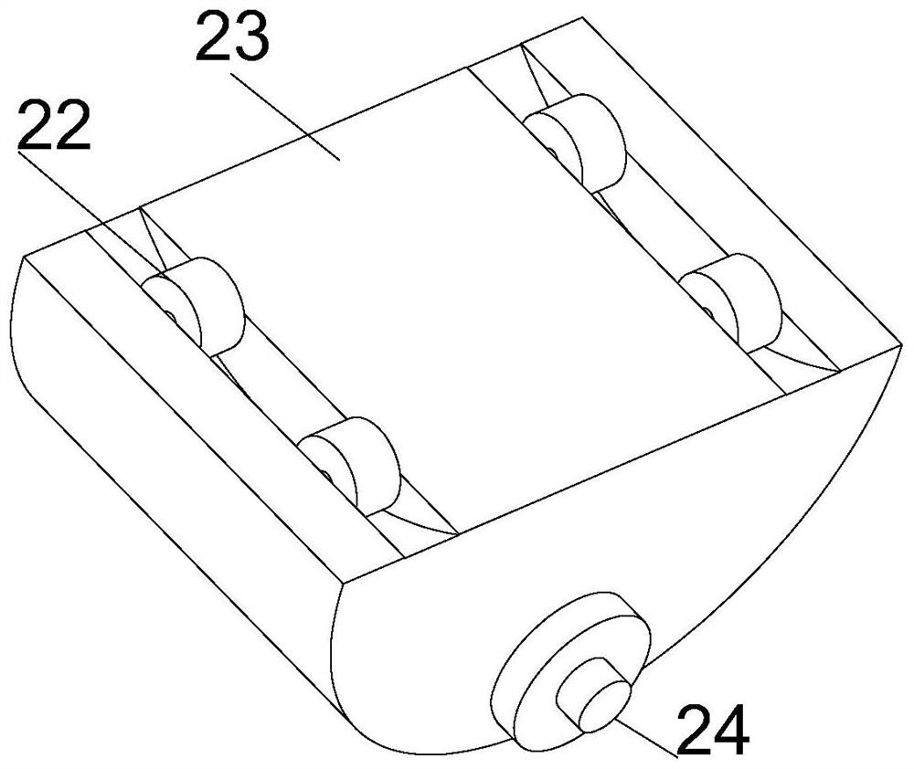
[0021]SeeFigure 1 ~ 3In the embodiment of the present invention, an ultra-high filling rate continuous dry ball mill, including a horizontally disposed support mounting plate 1, and the upper right upper end of the support mounting plate 1 is vertically provided with support mounting frame 25, support the upper end of the mounting frame 25. The rotating mounting plate 23 is provided by the support shaft 24, and the support mounting plate 1 is disposed laterally, and the two ends of the rotating mounting cylinder 18 are configured to rotate the shutter 20, and the outer end of the rotation gate 20 is connected. The buckle 19 is fixed to the rotating mounting cartridge 18, and the upper tethanum of the rotating mounting plate 23 is provided by the rotating shaft to set the finite bonding wheel 22, and the left and rear sides are located outside the outer side of the rotating mounting cartridge 18. The rotating ring 21, the left end of the support mounting plate 1 is vert

Example Embodiment

[0023]Example 2

[0024]On the basis of the first example, the drive motor 2 is activated such that the driving cone gear 3 mates engagement transmission, realizing the restricted rotation shaft 5 and the lifting stud 8 synchronously, the lifting screw 9 cooperates with the elevator The column 8 achieves lifting adjustment, at which time the rotating support plate 10 and its support guide wheel 11 mitigate the inclination of the positioning support plate 12, it is finally achieved the inclination of the rotating mounting tube 18, and the introduction and export of the ball milling feedstock, rotate mounting When the barrel 18 is rotated, the support rotating shaft 24 and the rotating mounting plate 23 make the rotation process continuously stabilize and does not affect the progression of the ball mill.


PUM


Abstract

The invention relates to the field of ball mills, in particular to a continuous dry-method ball mill with an ultrahigh filling rate. The continuous dry-method ball mill comprises a horizontally-arranged supporting mounting plate, wherein a supporting mounting frame is vertically arranged at the upper right end of the supporting mounting plate, a rotating mounting plate is arranged at the upper end of the supporting mounting frame through a supporting rotating shaft, a rotating mounting cylinder is transversely arranged right above the supporting mounting plate, rotating gates are symmetrically arranged at the two ends of the rotating mounting cylinder, the outer ends of the rotating gates are fixed to the rotating mounting cylinder through connecting buckles, and a transmission mounting cylinder is vertically arranged at the left end of the supporting mounting plate. Through a swing adjustment structure, the guide-in and guide-out speeds of raw materials to be subjected to ball milling treatment are controlled to achieve continuous ball milling operation of the continuous dry-method ball mill in cooperation with simultaneous rotation transmission, adaptive adjustment of the continuous dry-method ball mill to different ball milling qualities is achieved through a combined type guide mounting structure, and combined type ball milling operation can be carried out by replacing the ball milling materials with different diameters, so that the quality and the efficiency of ball milling operation are obviously improved.

Description


Claims


Application Information

Patent Timeline
Owner 淄博锦岳机械制造有限公司
Why Eureka
Try Eureka