Three-phase 18/16-pole bearingless switched reluctance motor

A switched reluctance motor and bearingless technology, which is applied in the direction of electromechanical devices, electrical components, electric components, etc., can solve the problems of limited popularization and application, dead zone, and existence of starting torque, etc., and achieves the reduction of stator core loss and simple control , the effect of increasing the output power

Active Publication Date: 2021-07-23
NANJING UNIV OF POSTS & TELECOMM
View PDF3 Cites 0 Cited by
  • Summary
  • Abstract
  • Description
  • Claims
  • Application Information

AI Technical Summary

Benefits of technology

The technical effect described by this patented technology relates to improving the performance and efficiency of an electric machine used for driving loads such as vehicles or machinery. It achieves these improvements through controlling both torques and forces while also simplifying its design with fewer components than traditional machines that use multiple windings per phase. This results in improved energy utilization compared to conventional designs without any changes made during operation due to reduced iron losses caused by increased eddy current flow within certain parts of the electrical device's winding.

Problems solved by technology

This patented technical problem addressed in this patents is how to design an improved bearingslessly controlled switched inductance machine without compromising its ability for efficient use under various conditions like high speeds or extreme temperatures while maintaining excellent load capacity capabilities.

Method used


Image

  • Three-phase 18/16-pole bearingless switched reluctance motor
  • Three-phase 18/16-pole bearingless switched reluctance motor
  • Three-phase 18/16-pole bearingless switched reluctance motor

Examples


Embodiment Construction

[0025] The technical scheme of a three-phase 18 / 16 pole bearingless switched reluctance motor of the present invention will be described in detail below in conjunction with the accompanying drawings:

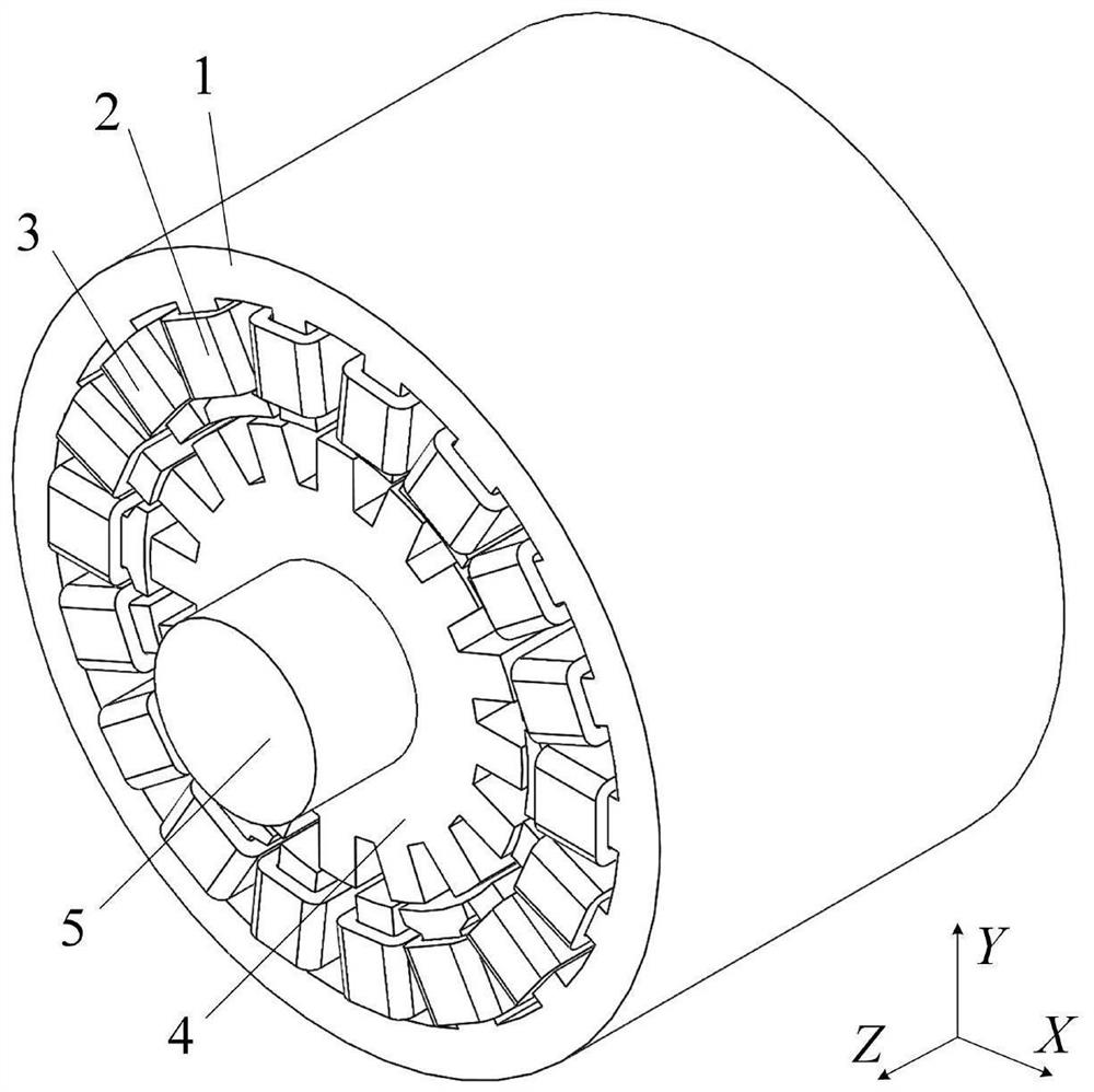
[0026] like figure 1 As shown, it is a three-dimensional structural schematic diagram of a three-phase 18 / 16 pole bearingless switched reluctance motor of the present invention, wherein, 1 is a stator, 2 is a suspension coil, 3 is a torque coil, 4 is a rotor, 5 is a rotating shaft, X, Y and Z are the three coordinate axes of the Cartesian coordinate system, respectively.

[0027] The three-phase bearingless switched reluctance motor includes a stator, a torque coil, a suspension coil, a rotor and a rotating shaft; the rotor is sleeved on the rotating shaft, and the rotor is arranged in the stator;

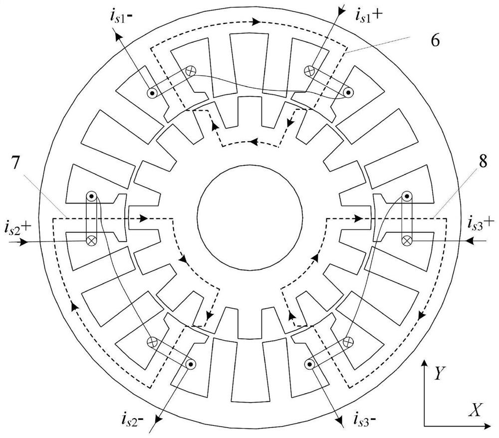
[0028] The stator has a salient pole structure, including 12 torque teeth and 6 suspension teeth, a total of 18 teeth; the 6 suspension teeth are evenly distributed in space, and t


PUM


Abstract

The invention discloses a three-phase 18/16-pole bearingless switched reluctance motor. According to the invention, torque windings on torque teeth are used for generating output torque, and suspension windings on the suspension teeth are used for generating radial suspension force; due to the fact that the pole arc angle of the suspension teeth is equal to a rotor periodic angle, the inductance of the suspension windings is constant, and the motion electromotive force of the suspension windings is zero, so the suspension winding does not generate torque, and then natural decoupling of the torque and the suspension force can be achieved structurally; a traditional switched reluctance motor driving mode is adopted for rotation control, and suspension control is similar to a traditional electromagnetic bearing control mode, so control is simple, and good suspension performance is obtained; only one coil is wound on each tooth, so a structure is simple, machining and assembling are convenient, and a multi-rotor-tooth-number structure facilitates reduction of torque pulsation and increase of output power; moreover, torque and suspension magnetic circuits are both of a short magnetic circuit structure, so iron core loss can be reduced; and the magnetic flux direction of a stator yoke part does not change when the motor operates, so the stator iron core loss can be further reduced.

Description


Claims


Application Information

Patent Timeline
Owner NANJING UNIV OF POSTS & TELECOMM
Why Eureka
Try Eureka