Ball-holding type locknut
A technology of anti-loosening nut and bead holding type, which is applied in the direction of nuts, screws, bolts, etc., can solve the problems of complicated operation and inconvenient production, and achieve the effect of convenient disassembly
- Summary
- Abstract
- Description
- Claims
- Application Information
AI Technical Summary
Problems solved by technology
Method used
Image

Examples
Example Embodiment
[0044] Example 1.
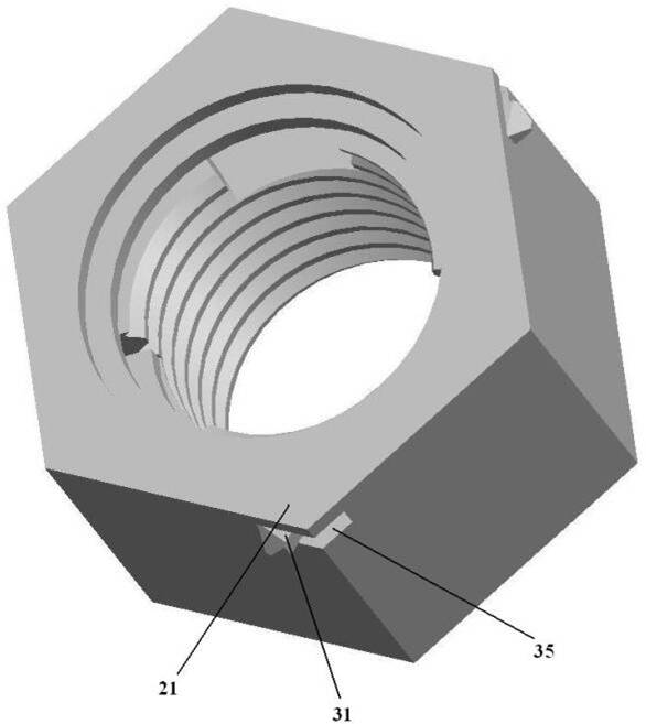
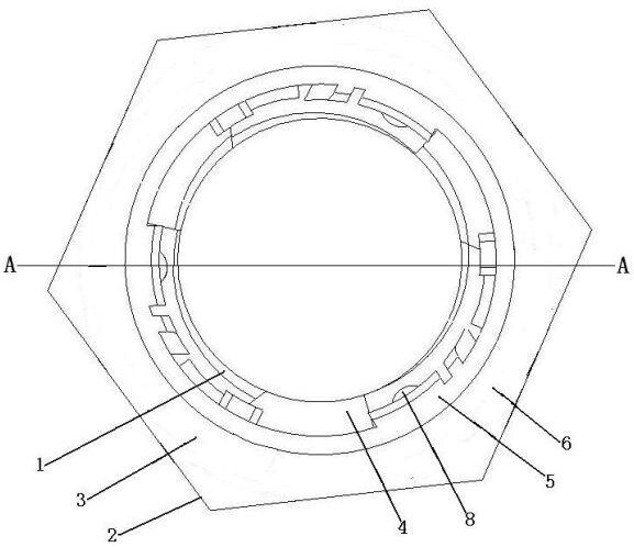
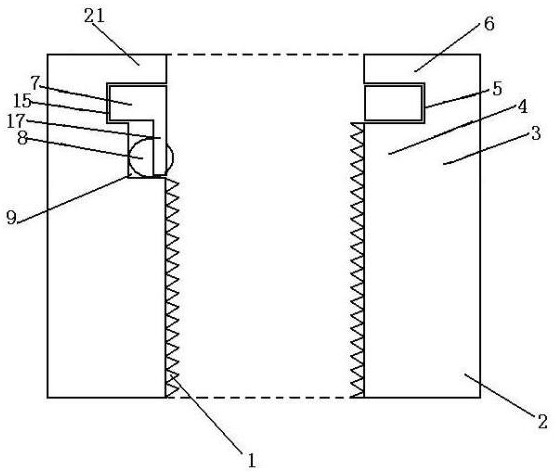
[0045] As shown, a bead anti-lane nut comprising a nut, the nut is a polygonal column having a centrally circular hole, and an inner ribbon wall surface of the central circular aperture is provided. SUMMARY The nut is divided into a fastening portion 2 and a non-loosening portion 3 of the fastening portion 2, i.e., the fastening portion 2 and the original nut on the inner ring wall. The thread structure is the same, and the internal thread 1 is complete, maintaining the original structure constant; the anti-loose portion 3 is based on the internal thread 1 of the original inner ring to the starting point 2 as the starting point from within. The clasp portion 4, the clamping portion 5, and the card portion 6 are disposed in sequentially connected, and the clamping portion 5 is provided with a rotatable rotary clamping loop 7, and further includes steel beads 8; A slope 9 is provided on the inner ring wall where the slant groove portion 4 is located, and the slope 9
Example Embodiment
[0047] Example 2.
[0048] Further, including the bayonet, if Figure 7 , 8, 9, the cardial disassembly device includes a card pin 22, a positioning pin 23, and a bayonet 24, which is fixed to the upper side of the clamping loop 7; the positioning pin 23 is there. Width rod part; the bayonet 24 is disposed on the circular chuck 21 for passing the card pin 22 and the positioning pin 23, the card pin 22 is reserved in the bayonet 24, the positioning The pin 23 is an allocated, which is used, so that the overall constituting the bayonet disassembled beads anti-pine nut; after normal fastening, the card pin 22 fixed on the upper side of the clamping ring 7 is reserved in the bayonet In 24, the card pin 22 can also be extended to constitute the ear handle 25, and the spin position reserved in the bayonet 24; when the disassembly is required, the positioning pin 23 against the card pin 22 is close to the rotation orientation. On the side, or pinch the ear handle 25, then push the card pin 2
Example Embodiment
[0049] Example 3.
[0050] There are many programs on the dismountment device, such as Figure 10 , 11 12, 13, can also be used with a card hole disassembly device including a card hole 26, a positioning hole 27, an arcuate slot 28, and a column 29, the card hole 26 is a drill. At the through hole on the clavicle 7, the positioning hole 27 is a blind hole that drills the non-turning groove portion 4 position, the arcuate slot 28 being a circular chuck. The through-shaped curved groove on 21, the length of the arcuate slot 28 is equal to 1-2 times the diameter of the steel bead 8, and the tail end of the arcuate groove 28 is aligned with the positioning hole, the tail end. The first end of the curved pass groove 28 is the tightening direction end aligning the card hole 26, the column 29 is an all-in-back, which is used when disassembling; when it is required to be disassembled, the column 29 passes through the curved pass groove 28. The first end is inserted into the card hole 26, and
PUM
 Abstract
Description
Claims
Application Information
 - R&D Engineer
- R&D Manager
- IP Professional
- Industry Leading Data Capabilities
- Powerful AI technology
- Patent DNA Extraction
Browse by: Latest US Patents, China's latest patents, Technical Efficacy Thesaurus, Application Domain, Technology Topic.
© 2024 PatSnap. All rights reserved.Legal|Privacy policy|Modern Slavery Act Transparency Statement|Sitemap