Spin welding system

A technology of rotary welding and welding mechanism, applied in welding equipment, welding equipment, auxiliary welding equipment, etc., can solve the problems of high labor cost and low efficiency, and achieve the effect of overcoming high cost

Active Publication Date: 2021-08-31
江苏申牌万向轮有限公司
View PDF9 Cites 0 Cited by
  • Summary
  • Abstract
  • Description
  • Claims
  • Application Information

AI Technical Summary

Benefits of technology

This patented technology allows for automatic welds on work pieces without requiring manual labor costs while also being able to perform advanced functionality like intelligence. It uses an improved way to fix these works onto a special machine called a tool holder system (PTS). By attaching this PTS to the work piece's surface beforehand, there may only require one step during assembly instead of multiple steps needed with conventional methods such as spot-welding techniques. Overall, this innovation improves productivity and reduces manufacturing time compared to current ways.

Problems solved by technology

This patented problem addressed by this patents relates to traditional methods for manually welds on materials like metal pipes that require skilled workers' hands during assembly processes due to their time-consuming nature. There has been some effort towards developing a more efficient method with fewer steps than current ways such as automatic arc welders but still requiring human operators to perform these tasks effectively.

Method used


Image

  • Spin welding system
  • Spin welding system
  • Spin welding system

Examples


Embodiment 1

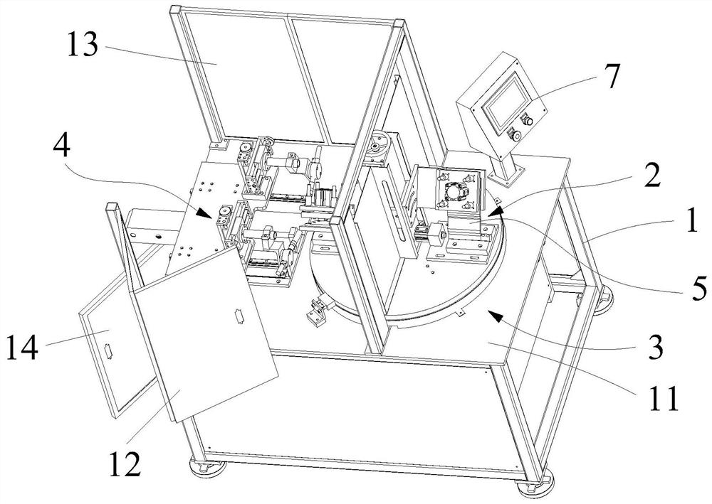
[0039] figure 1 It is a structural diagram of the spin welding system of the present invention.

[0040] In this example, if figure 1As shown, the present embodiment provides a rotary welding system, which includes: a control module, a mounting bracket 1, a workpiece fixing mechanism 2, a turntable mechanism 3 and a welding mechanism 4; wherein the turntable mechanism 3 and the welding mechanism 4 are horizontally arranged on On the mounting bracket 1, the workpiece fixing mechanism 2 is located on the turntable mechanism 3, and the workpiece fixing mechanism 2, the turntable mechanism 3 and the welding mechanism 4 are all electrically connected to the control module; the workpiece fixing mechanism 2 is suitable for placing Welding the workpiece 5, the control module is suitable for controlling the workpiece fixing mechanism 2 to lock the workpiece 5 to be welded; the control module is suitable for driving the turntable mechanism 3 to drive the workpiece fixing mechanism 2 to ro


PUM


Abstract

The invention particularly relates to a spin welding system. The spin welding system comprises a control module, a mounting bracket, a workpiece fixing mechanism, a turntable mechanism and a welding mechanism. The workpiece fixing mechanism is used for placing a to-be-welded workpiece, and the control module controls the workpiece fixing mechanism to lock the to-be-welded workpiece. The control module drives the turntable mechanism to drive the workpiece fixing mechanism to rotate, so that the to-be-welded workpiece fixed on the workpiece fixing mechanism rotates to a welding area of the welding mechanism. The control module further controls the welding mechanism to weld the to-be-welded workpiece in the welding area. The to-be-welded workpiece is fixed through the workpiece fixing mechanism and driven to the welding area of the welding mechanism through the turntable mechanism, the welding mechanism is intelligently controlled to weld the to-be-welded workpiece, the to-be-welded area on the to-be-welded workpiece can be automatically aligned, the intelligent welding function is achieved, and the problems of high cost, low efficiency and risks caused by a traditional manual welding mode are solved.

Description


Claims


Application Information

Patent Timeline
Owner 江苏申牌万向轮有限公司
Why Eureka
Try Eureka