Cutting device for machining of mechanical parts

A technology for cutting devices and mechanical accessories, applied in shearing devices, metal processing equipment, accessories of shearing machines, etc., can solve the problems of inconvenient access to accessories, inability to maintain a stable position of accessories, and affecting the accuracy of cutting dimensions of accessories, etc. Achieve the effect of solving the unstable position, convenient and quick access, and efficient clamping

Inactive Publication Date: 2021-09-28
江苏融信通供应链管理有限公司
View PDF0 Cites 0 Cited by
  • Summary
  • Abstract
  • Description
  • Claims
  • Application Information

AI Technical Summary

Benefits of technology

The technical feature described in this new cutter has two main advantages - it does not have any instability during solution with machine tools or other objects being worked on, making them easier to use without getting stuck between things like bolts or screws. It simplifies assembly processes compared to traditional methods such as sawing or drilling holes.

Problems solved by technology

This patented technical solution described in the text allows machinery part manufacturers to cut mechanisms while ensuring they stay securely located throughout the entirety of the machine's operation without being affected by external factors such as vibrations or other movements caused by its own motion.

Method used


Image

  • Cutting device for machining of mechanical parts
  • Cutting device for machining of mechanical parts
  • Cutting device for machining of mechanical parts

Examples


Embodiment Construction

[0019] The following will clearly and completely describe the technical solutions in the embodiments of the present invention with reference to the accompanying drawings in the embodiments of the present invention. Obviously, the described embodiments are only some, not all, embodiments of the present invention.

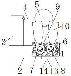
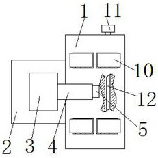
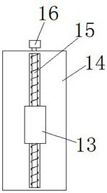
[0020] In this embodiment one, refer to Figure 1-4 , a cutting device for processing mechanical parts, comprising a base 14, the upper surface of the base 14 is provided with a straight groove along its length direction, and a lead screw 15 is installed in the straight groove through the screw bearing to rotate, and the lead screw 15 is screwed with a moving Seat 13, the top of mobile seat 13 is provided with console 1, and the inside of console 1 is respectively provided with driving wheel 6 and driven wheel 7 that keep mutually meshing relationship near its two ends, the driving wheel 6 and driven wheel 7 The center is respectively provided with a rotating shaft 8, a


PUM


Abstract

The invention relates to the technical field of machining of mechanical parts, in particular to a cutting device for machining of mechanical parts. The cutting device for machining of the mechanical parts comprises a base; a control table capable of linearly moving is arranged on the base; opposite opening clamps are arranged on two sides of a table top of the control table; a mounting frame is arranged on the table top of a mounting table; a cantilever capable of overturning is arranged at the top of the mounting frame; the cantilever extends towards the table top of the control table, and a cutting machine is arranged on the end portion of the cantilever; and the cutting machine is located at the middle position above the table top of the control table. The cutting device solves the problem that the position is not stable during cutting of the mechanical parts, and meanwhile manual taking is not convenient; the design of the opposite opening clamps is put forwards in the cutting device, it can be guaranteed that the mechanical parts arranged in the cutting device are efficiently clamped, workers can also conveniently and rapidly take the mechanical parts, and the cutting device is simple and practical.

Description


Claims


Application Information

Patent Timeline
Owner 江苏融信通供应链管理有限公司
Why Eureka
Try Eureka