Dispensing stirrer

A mixer and dispensing technology, applied in the field of medical equipment, can solve the problems of increasing the labor intensity of medical staff, failing to meet the actual needs of use, and inability to mix medicine liquids, etc., to improve the efficiency of dispensing work, increase the stability of movement, and facilitate the extraction of medicines. liquid effect

Pending Publication Date: 2021-11-05
倪荷春
View PDF1 Cites 0 Cited by
  • Summary
  • Abstract
  • Description
  • Claims
  • Application Information

AI Technical Summary

Problems solved by technology

[0004] The device disclosed in this patent cannot mix the liquid medicine inside the medicine bottle, and requires medical staff to manually dispens

Method used


Image

  • Dispensing stirrer
  • Dispensing stirrer
  • Dispensing stirrer

Examples


Embodiment Construction

[0038] The following are specific embodiments of the present invention and in conjunction with the accompanying drawings, the technical solutions of the present invention are further described, but the present invention is not limited to these embodiments.

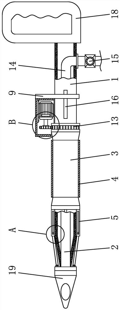
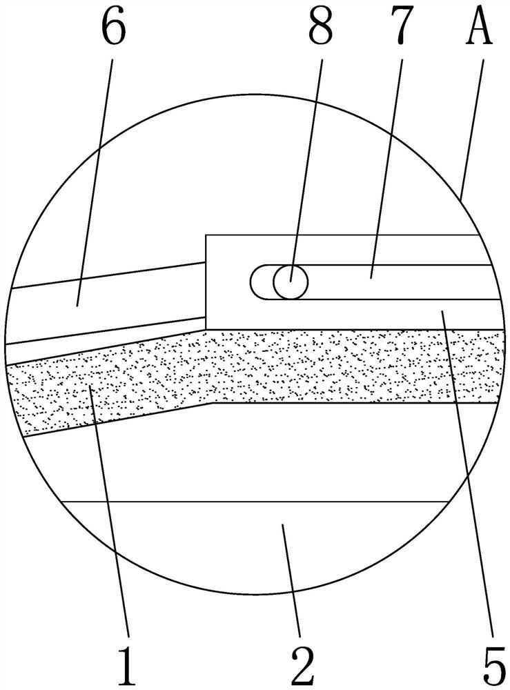
[0039] Such as Figure 1-Figure 6 As shown, the dispensing mixer includes a dispensing cylinder 1, a puncture needle 2 is arranged inside the dispensing cylinder 1, a needle 19 is fixedly connected to the left end of the dispensing cylinder 1, and a sleeve 3 is set on the outside of the dispensing cylinder 1, and the sleeve 3 The outer sleeve of the sleeve 4 is provided with an outer sleeve 4, the left side of the sleeve 3 is fixed with an adjustment rod 5, and the adjustment rod 5 and the outer sleeve 4 are hinged, the right side of the needle 19 is provided with a movable rod 6, and the surface of the adjustment rod 5 is opened. There is a bar-shaped groove 7, the right end of the movable rod 6 is fixedly connected with a c


PUM


Abstract

The invention provides a dispensing stirrer and belongs to the technical field of medical appliances. The dispensing stirrer is used for solving the problem of relatively low dispensing efficiency of an existing dispensing device caused by manual dispensing of medical staff due to the fact that medicine liquid in a medicine bottle cannot be mixed. The dispensing stirrer comprises a dispensing cylinder, wherein a puncture needle is arranged inside the dispensing cylinder, a needle head is fixedly connected to the left end of the dispensing cylinder, a sleeve is arranged at the outer side of the dispensing cylinder in a sleeve mode, an outer sleeve is arranged at the outer side of the sleeve in a sleeve mode, an adjusting rod is fixed to the left side of the sleeve and hinged to the outer sleeve, a movable rod is arranged at the right side of the needle head, a strip-shaped groove is formed in the surface of the adjusting rod, and the right end of the movable rod is fixedly connected with a connecting block. The dispensing stirrer has the advantages that the medicine liquid can be mixed and stirred, the uniformity of the medicine liquid is improved, and the labor intensity of medical workers can be reduced, so that the working efficiency of dispensing can be increased, and convenience is brought to the medical workers.

Description


Claims


Application Information

Patent Timeline
Owner 倪荷春
Why Eureka
Try Eureka