Airborne laser radar three-dimensional scanning device with long distance measurement and high precision
A technology of laser radar and three-dimensional scanning, which is applied in the direction of radio wave measurement systems and instruments, can solve the problems of high descending acceleration, low efficiency, and increased cost, and achieve the effects of removing occlusion, convenient use, and improving work efficiency
- Summary
- Abstract
- Description
- Claims
- Application Information
AI Technical Summary
Problems solved by technology
Method used
Image

Examples
Embodiment 1
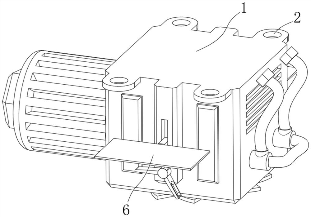
[0033] see Figure 1-Figure 10 , an airborne laser radar three-dimensional scanning device with long range and high precision in the illustration, including a body 1, a protective device 5, a driving device 6 and a cleaning device 7, and the body 1 is provided with a plurality of mounting buckles 2. The bottom surface of the body 1 is provided with a high-definition camera 3, and the body 1 is provided with an annular lifting groove 4, and the protective device 5 is installed on the body 1 to protect the high-definition camera 3 when the body 1 lands at a high speed. To protect against being scratched by particles in the air, the driving device 6 is installed on the body 1, and is used to drive the protection device 5 to run by the wind force when the body 1 falls at a high speed, and the cleaning device 7 is installed on the body 1, It is used to clean the surface of the high-definition camera 3 when the protective device 5 is running.
[0034] The protection device 5 includes a
Embodiment 2
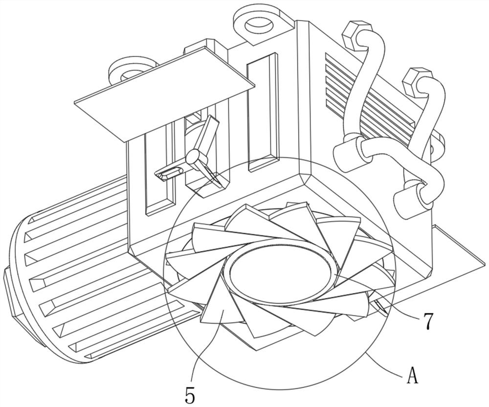
[0040] see Figure 4-Figure 10 Embodiment 2 is described. This embodiment will further illustrate Embodiment 1. The driving device 6 in the illustration includes a windshield 26, and the side of the body 1 is provided with a device groove 27, and the device groove 27 is rotatably connected with a gear 28, the windshield 26 is fixedly connected with a connecting rod 29 slidingly connected with the device groove 27, and the connecting rod 29 is fixedly connected with a first rack 30 slidingly connected with the device groove 27. The rack 30 is engaged with the gear 28, and a second rack 31 engaged with the gear 28 is slidably connected in the device groove 27, and the bottom end of the second rack 31 is connected to the top surface of the second limiting ring 20. Slidingly connected, the body 1 is provided with a driving member 32 for driving the bevel gear disc 11 to rotate.
[0041] The driving member 32 includes a rotating shaft 33 that runs through one side of the body 1 and i
Embodiment 3
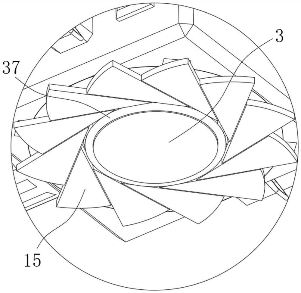
[0047] see Figure 6-Figure 8 and Figure 11 Illustrate embodiment 3, this embodiment will further illustrate embodiment 1, and the cleaning device 7 in the drawing comprises elastic cleaning rope 37, and described elastic cleaning rope 37 is circular, is fixedly connected with on described elastic cleaning rope 37 The first pull cord 38 is fixedly connected to the top end of the inner wall of the lifting ring 8 , and the second pull cord 39 is fixedly connected to the bottom end of the inner wall of the lifting ring 8 on the elastic cleaning rope 37 .
[0048] In this embodiment, when the lifting ring 8 descends: it will drive the second pull cord 39 to pull the elastic cleaning rope 37 to move down, and the elastic cleaning rope 37 in the downward movement process will slide to the lower surface of the high-definition camera 3, and be subjected to its own elasticity Shrink and stretch the second stay cord 39, now the elastic cleaning cord 37 will complete the cleaning that fit
PUM
 Abstract
Description
Claims
Application Information
 - R&D Engineer
- R&D Manager
- IP Professional
- Industry Leading Data Capabilities
- Powerful AI technology
- Patent DNA Extraction
Browse by: Latest US Patents, China's latest patents, Technical Efficacy Thesaurus, Application Domain, Technology Topic.
© 2024 PatSnap. All rights reserved.Legal|Privacy policy|Modern Slavery Act Transparency Statement|Sitemap