Intelligent gantry welding machine and gun aligning and positioning method thereof
A technology for welding torches and positioning components, applied in welding equipment, welding accessories, characteristics of welding rods, etc., can solve the problems of low degree of automation and the inability of gantry welding machines to quickly achieve accurate welding and positioning of welding points, so as to reduce operation steps and improve performance. The effect of production efficiency
- Summary
- Abstract
- Description
- Claims
- Application Information
AI Technical Summary
Benefits of technology
Problems solved by technology
Method used
Image

Examples
Embodiment 1
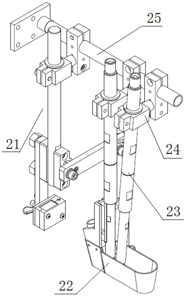
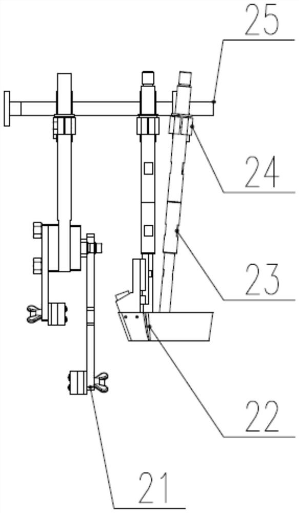
[0052] This embodiment provides a quick positioning assembly joints, such as Figure 1 to 6 , The torch including a connecting rod assembly further comprises a laser tracker;
[0053] The laser tracker assembly disposed in the torch the connecting rod;
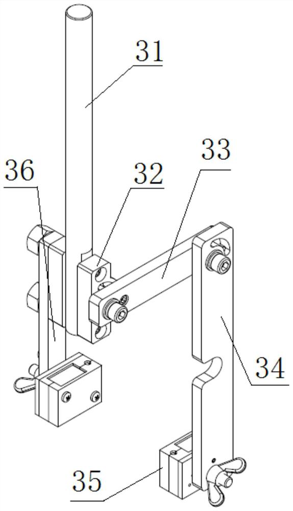
[0054] The laser tracker assembly includes a first link, the first and second components, the first link provided in an upper portion of the torch connecting rod, said first and second components separate in the lower portion of the first link sides; said first and second components each include a connecting rod with a laser and a laser, the laser is a laser connected by a connecting rod and a lower side surface of the first link, said laser and the laser rod is connected pivotally connected: the laser can rotate about itself;
[0055] The two lasers are on a plane parallel to, the rotation direction of the two lasers are perpendicular to the longitudinal direction of the torch connecting rod.
[0056] With respect to the prior art, s
Embodiment 2
[0063] This example further optimized on the basis of Example 1, there is provided a positioning method for rapid positioning assembly of joints, such as Image 6 As shown, including the following steps:
[0064] Step a: control components of the torch gun;
[0065] Step II: After completion of the gun, and open two rotating lasers, each laser hit two lasers on a workpiece, and to record relative distance between the initial laser beam and the workpiece, the laser is divided into two lasers on both sides of the solder joint ;
[0066] Step Three: locked laser, so that the angle between the two lasers remain unchanged;
[0067] Step IV: After the completion of locking, welding is started, the two lasers keep track of the relative distance between the laser and the workpiece, then an initial relative distance and the relative distance of the track has been compared and calculated offset value;
[0068] Step Five: Offset offset value is determined: The magnitude of the deviation value, t
Embodiment 3
[0087] The present embodiment provides an intelligent welding gantry, such as Image 6 and Figure 7 Shown, it comprises a travel rail, further comprising a gantry;
[0088] The gantry leg walking frame by articulating and travel rail, the travel gantry movable along the longitudinal direction of the rail; the gantry is provided with a transverse linear rails, the linear rails slidably connected with a carriage assembly; also a linear slide longitudinally on said carriage assembly, said longitudinal guide slidably connected to the column assembly linear slide;
[0089] The lower end is provided with guide column assembly head assembly, the head assembly positioning assembly comprises a quick joints;
[0090] The lead wire assembly and with a recycling component assembly, said wire feeder assembly for automatically feeding the wire, the recovery component for recovering solder.
[0091] In the present embodiment, the bottom of the gantry carts traveling welder for walking frames, walkin
PUM
 Abstract
Description
Claims
Application Information
 - R&D Engineer
- R&D Manager
- IP Professional
- Industry Leading Data Capabilities
- Powerful AI technology
- Patent DNA Extraction
Browse by: Latest US Patents, China's latest patents, Technical Efficacy Thesaurus, Application Domain, Technology Topic.
© 2024 PatSnap. All rights reserved.Legal|Privacy policy|Modern Slavery Act Transparency Statement|Sitemap