Automatic circulation impact fatigue test device

An impact fatigue and testing device technology, applied in measuring devices, using repetitive force/pulsation force to test material strength, and testing of mechanical parts, etc. Improve circulation efficiency and not easy to loosen

Pending Publication Date: 2021-12-21
NORTHWESTERN POLYTECHNICAL UNIV
View PDF24 Cites 3 Cited by
  • Summary
  • Abstract
  • Description
  • Claims
  • Application Information

AI Technical Summary

Problems solved by technology

[0005] The purpose of the present invention is to provide an automatic cycle impact fatigue test device to solv

Method used


Image

  • Automatic circulation impact fatigue test device
  • Automatic circulation impact fatigue test device
  • Automatic circulation impact fatigue test device

Examples


Embodiment

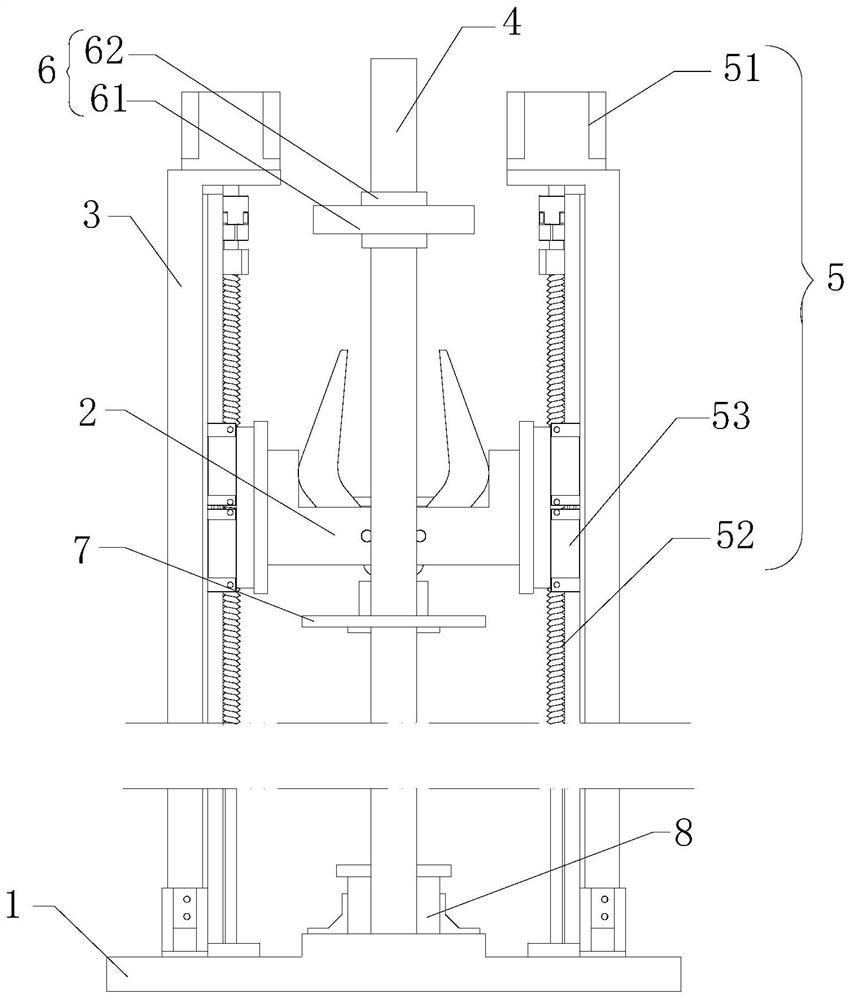
[0042] like figure 1 As shown, an automatic cyclic impact fatigue test device includes: a base 1, a clamping assembly 2, a support plate 3 vertically arranged on the base 1 and located on both sides of the clamping assembly 2, vertically arranged on the base 1 and connected to the support The guide rod 4 parallel to the plate 3, the lifting drive assembly 5 arranged on the top of the support plate 3 and used to drive the clamping assembly 2 to move up and down along the support plate 3, is sleeved on the guide rod 4 and used to control the opening and closing of the clamping assembly 2 The opening and closing assembly 6, and the impact assembly 7 sleeved on the guide rod 4 and clamped by the clamping assembly 2. The base 1 is used to support the entire test device, the clamping assembly 2 is used to clamp the impact assembly 7 on the guide rod 4, the opening and closing assembly 6 is used to drive the clamping assembly 2 to open and close, the guide rod 4 acts as a guide, and the


PUM


Abstract

The invention discloses an automatic circulation impact fatigue test device. The test device comprising a base, a clamping assembly, supporting plates vertically arranged on the base and located on the two sides of the clamping assembly, guide rods vertically arranged on the base and parallel to the supporting plates, lifting driving assemblies arranged at top ends of the supporting plates and used for driving the clamping assembly to ascend and descend along the supporting plates, an opening and closing assembly which is arranged on the guide rod in a sleeving mode and used for controlling opening and closing of the clamping assembly, and an impact assembly which is arranged on the guide rod in a sleeving mode and clamped by the clamping assembly, wherein the opening and closing assembly is located above the impact assembly, the impact assembly is slidably connected with the guide rod, and the clamping assembly is located between the opening and closing assembly and the impact assembly; a test placement assembly is arranged on the base, and the test placement assembly corresponds to the impact assembly. By arranging the lifting driving assembly, the clamping assembly, the opening and closing assembly, the impact assembly and the test placement assembly, circulation efficiency of the impact fatigue test device is improved, and meanwhile, accuracy of experimental data is improved.

Description


Claims


Application Information

Patent Timeline
Owner NORTHWESTERN POLYTECHNICAL UNIV
Why Eureka
Try Eureka