Automatic magnetic feeding device for brushless rotor

A magnetic device and rotor technology, applied in electromechanical devices, manufacturing stator/rotor bodies, electric components, etc., can solve the problems of demagnetization, demagnetization, low yield, etc., and achieve full automation and improve production efficiency. Effect

Pending Publication Date: 2021-12-21
深圳市攀鑫智能科技有限公司
View PDF6 Cites 0 Cited by
  • Summary
  • Abstract
  • Description
  • Claims
  • Application Information

AI Technical Summary

Benefits of technology

The present invention provides an improved method for producing high performance permanent magnets with better quality control during manufacturing processes compared to existing methods that require manual labor or expensive equipment such as sinter machines. This results in more efficient use of materials while improving productivity.

Problems solved by technology

Technological Problem: Permanent-Magnet Synchronous Motor (PMSM), due to its simplicity, lower costs compared to other types of machines like AC induction or direct current drives, can provide better performance without requiring extra components such as an external coil or brushing system. However, this design poses challenging manufacturing issues when assembling them together. Additionally, there may exist potential risks associated with handling these parts safely while they're being made.

Method used


Image

  • Automatic magnetic feeding device for brushless rotor
  • Automatic magnetic feeding device for brushless rotor
  • Automatic magnetic feeding device for brushless rotor

Examples


Embodiment

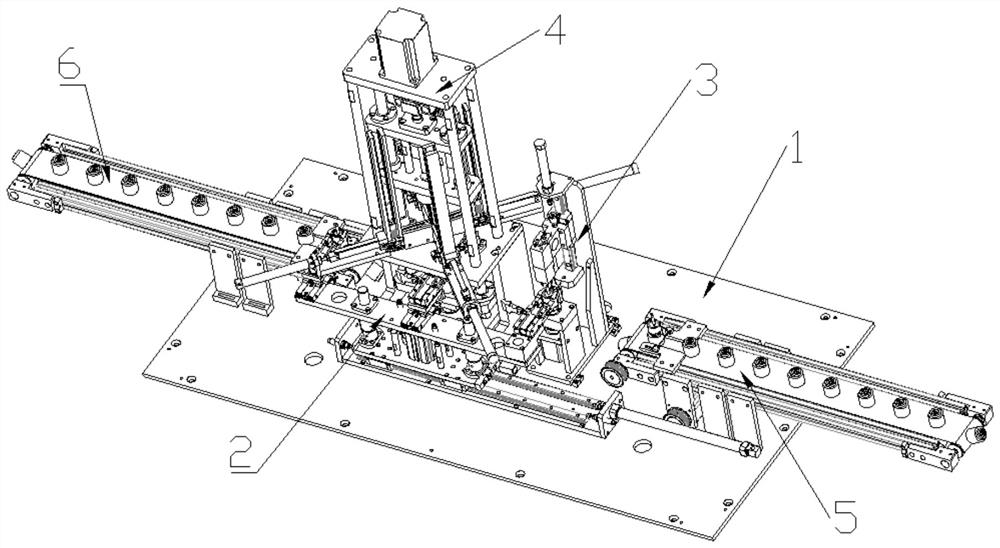
[0042] Such as Figure 1-9 The illustrated automatic magnetizing device for a brushless rotor includes a frame 1 on which a feeding mechanism, a grabbing mechanism 2, a positioning mechanism 3 and a magnetizing mechanism 4 are arranged, and the feeding mechanism includes a feeding mechanism Mechanism 5 and discharging mechanism 6, the grasping mechanism 2 and the magnetizing mechanism 4 are all arranged between the feeding mechanism 5 and the discharging mechanism 6, and the positioning mechanism 3 is arranged on the inlet Between the feeding mechanism 5 and the magnetizing mechanism 4.

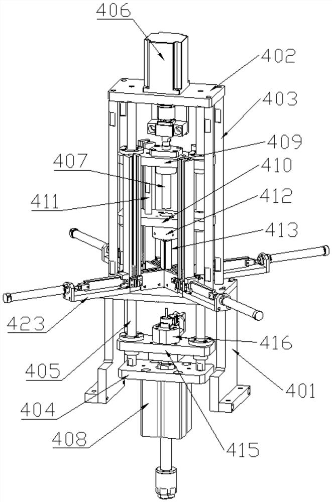
[0043] Specifically, the magnetization mechanism 4 includes a magnetization fixing seat 401, the magnetization fixing seat 401 is arranged on the frame 1, and a magnetization motor fixing seat 402 is arranged above the magnetization fixing seat 401, so that The magneto fixing seat 402 is connected with the magnetizing motor fixing seat 402 through the first magnetizing connecting rod 403, the f


PUM


Abstract

The invention relates to the field of mechanical equipment, and particularly discloses an automatic magnetic feeding device for a brushless rotor. The device comprises a rack, and is characterized in that the rack is provided with a feeding mechanism, a grabbing mechanism, a positioning mechanism and a magnetic feeding mechanism; the feeding mechanism comprises a material input mechanism and a material output mechanism; the grabbing mechanism and the magnetic feeding mechanism are arranged between the material input mechanism and the material output mechanism; the positioning mechanism is arranged between the material input mechanism and the magnetic feeding mechanism; and a non-magnetic rotor is placed on the material input mechanism. According to the invention, the non-magnetic rotor is adopted to replace the traditional magnetic rotor, and the magnetic steel is automatically pressed into the magnetic hole of the rotor through the mutual cooperation of all the mechanisms, so that the process is fully automatic, the production efficiency is greatly improved, and the problem of magnetic loss of the brushless motor magnet in the production process because there is no magnetic material after several processes is solved.

Description


Claims


Application Information

Patent Timeline
Owner 深圳市攀鑫智能科技有限公司
Why Eureka
Try Eureka