Topological structure of power electronic transformer

A technology of power electronics and topology, applied in the field of transformers, can solve the problems of lack of fault detection and analysis devices, difficulty in finding fault sources, and affecting the efficiency of maintenance.

Pending Publication Date: 2022-01-18
HUBEI NORMAL UNIV
View PDF0 Cites 0 Cited by
  • Summary
  • Abstract
  • Description
  • Claims
  • Application Information

AI Technical Summary

Benefits of technology

The technical effect described in this patented describes various ways to improve the performance or reliability (F) of electric equipment such as converters used in electrical energy transmission systems. These improvements include improved design techniques that enhances their efficiency, prevention against failures caused by external factors like weather, temperature changes, vibrations, etc., increased monitoring capabilities, enhanced diagnostic tools, advanced error handling functions, and more efficient troubleshooting procedures.

Problems solved by technology

The technical problem addressed in this patented text relates to finding failures within power electronic converters after they have been used for transmitting power due to various factors such as insufficient supply of electricity caused by weather conditions or other environmental issues like fires. This can lead to reduced productivity and increased costs associated with maintaining equipment.

Method used


Image

  • Topological structure of power electronic transformer
  • Topological structure of power electronic transformer
  • Topological structure of power electronic transformer

Examples


Embodiment Construction

[0026] The following will clearly and completely describe the technical solutions in the embodiments of the present invention with reference to the accompanying drawings in the embodiments of the present invention. Obviously, the described embodiments are only some, not all, embodiments of the present invention. Based on the embodiments of the present invention, all other embodiments obtained by persons of ordinary skill in the art without making creative efforts belong to the protection scope of the present invention.

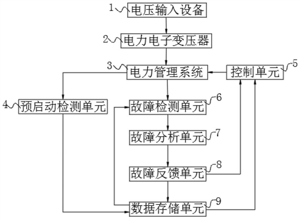
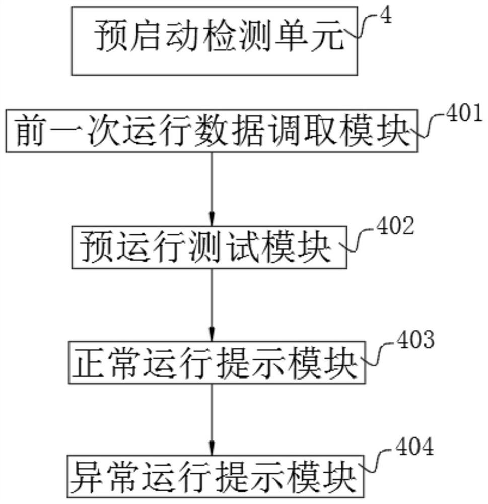
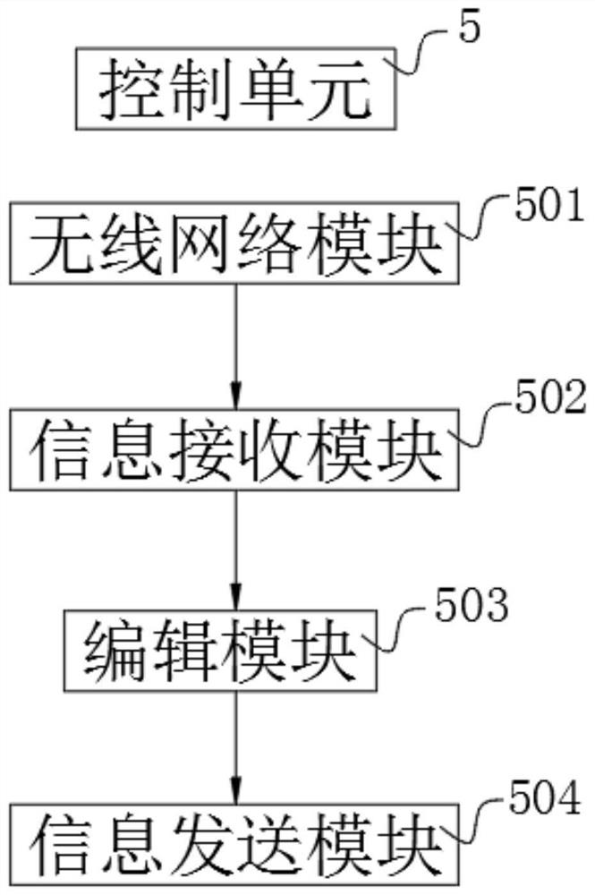
[0027] see Figure 1-6, the present invention provides a technical solution: a power electronic transformer topology, including a voltage input device 1, a power electronic transformer 2, a power management system 3, a pre-start detection unit 4, a control unit 5, a fault detection unit 6, and a fault analysis unit 7 and the fault feedback unit 8, the output end of the voltage input device 1 is connected to the input end of the power electronic transformer 2, the


PUM


Abstract

The invention discloses a topological structure of a power electronic transformer, and relates to the technical field of transformers. The topological structure comprises voltage input equipment, a power electronic transformer, a power management system, a pre-start detection unit, a control unit, a fault detection unit, a fault analysis unit and a fault feedback unit. Before the power electronic transformer is started to work, the transformer can be subjected to pilot operation before working through the pre-starting detection unit, and operation data is called from data through the previous operation data calling module, so that whether the transformer can work normally or not can be found in time, and then the situation that the power transformer needs to stop working for maintenance when the power transformer breaks down during working is avoided; the fault detection unit can extract the real-time working data of the transformer through the information extraction module, retrieves the data of the transformer during normal operation through the original data retrieval module, compares the data through the data comparison module, and then can detect the existing working condition of the transformer.

Description


Claims


Application Information

Patent Timeline
Owner HUBEI NORMAL UNIV
Why Eureka
Try Eureka