Laser welding method for spiral tube bundle type spray pipe

A technology of laser welding and helical tube bundles, applied in laser welding equipment, welding equipment, metal processing equipment, etc., can solve the problems of large thermal deformation of thin-walled nozzle welding, unfavorable profile accuracy, and unconcentrated power density, and achieve rapid Laser welding efficiency, good fusion width consistency, and concentrated heat input

Pending Publication Date: 2022-02-15
CAPITAL AEROSPACE MACHINERY
View PDF0 Cites 0 Cited by
  • Summary
  • Abstract
  • Description
  • Claims
  • Application Information

AI Technical Summary

Benefits of technology

This patented technology allows for better performance at very thin materials while maintaining their shape without causing damage or affects its properties during use. It uses different techniques such as lasers, ultrasonics, electric arc fusion (EA), plasma torches, etc., which can be used alone or together depending upon specific needs. By setting appropriate parameters based on these processes, it provides precise results that are suitable for various applications where there may have space constraints between components being joined.

Problems solved by technology

This patented describes different ways for improving the performance of a jetting device called Aerospace Engine's Nozzles that can perform various functions like propulsion or combustion engines. These improvements include improved durability against corrosion caused by extreme environments including high temperatures and pressures, reduced wear rates over longer periods without losing their effectiveness. Additionally, these modifications help maintain uniformity within certain areas where they were previously unsuccessful.

Method used


Image

  • Laser welding method for spiral tube bundle type spray pipe
  • Laser welding method for spiral tube bundle type spray pipe
  • Laser welding method for spiral tube bundle type spray pipe

Examples


Embodiment Construction

[0031] Exemplary embodiments of the present disclosure will be described in more detail below with reference to the accompanying drawings. Although exemplary embodiments of the present disclosure are shown in the drawings, it should be understood that the present disclosure may be embodied in various forms and should not be limited by the embodiments set forth herein. Rather, these embodiments are provided for more thorough understanding of the present disclosure and to fully convey the scope of the present disclosure to those skilled in the art. It should be noted that, in the case of no conflict, the embodiments of the present invention and the features in the embodiments can be combined with each other. The present invention will be described in detail below with reference to the accompanying drawings and examples.

[0032] The tube-bundle nozzle has high requirements for welding deformation control due to the thin welding wall and the total length of the weld reaching the ki


PUM


Abstract

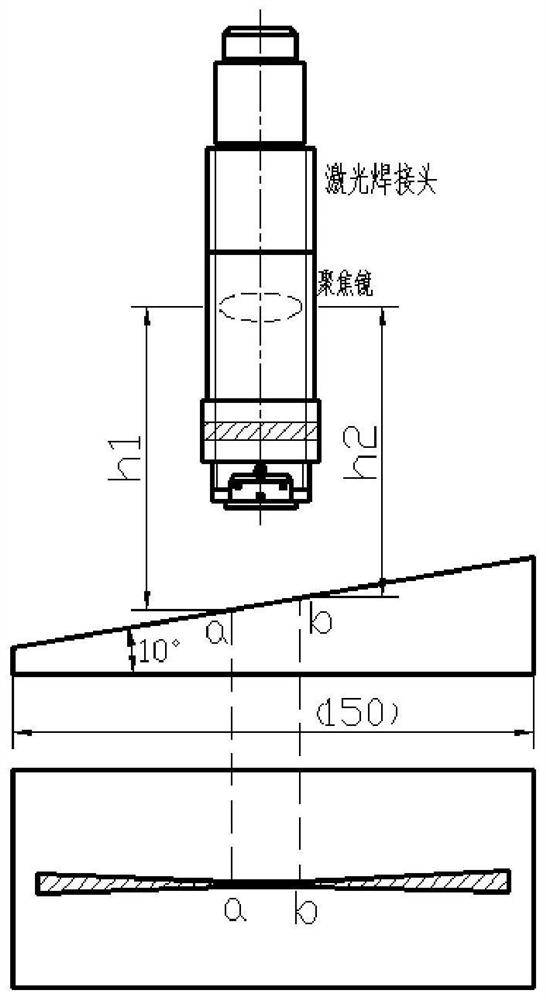
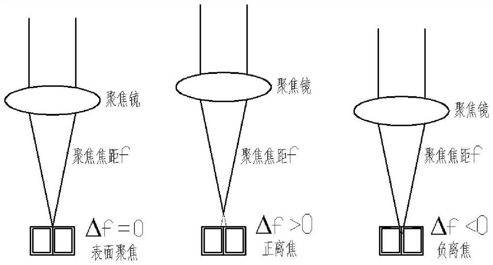
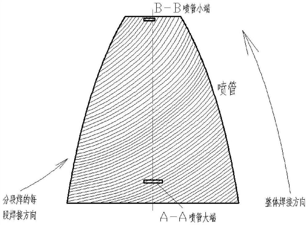
The invention discloses a laser welding method for a spiral tube bundle type spray pipe. The method comprises the following steps that firstly, the defocusing amount of laser welding of a thin-wall tube bundle is determined; secondly, the spray pipe is vertically clamped on a rotary positioner, the spray pipe is vertically welded, and the height of a laser welding head and the surface of the spray pipe is set according to the defocusing amount in the first step; and thirdly, a double-station robot executes a preset track program, the laser welding head is driven to move, and welding seams are welded till the welding of the large end of the spray pipe, the transition section of the spray pipe and the small end of the spray pipe is completed. According to the laser welding process for the spiral tube bundle type spray pipe, welding seam forming and welding process stability are facilitated, and the welding quality is guaranteed.

Description


Claims


Application Information

Patent Timeline
Owner CAPITAL AEROSPACE MACHINERY
Why Eureka
Try Eureka